Hitachi 55HDS69 Owners Guide - Page 12
Front/Rear/Side Panel Controls - no video
 |
UPC - 050585126848
View all Hitachi 55HDS69 manuals
Add to My Manuals
Save this manual to your list of manuals |
Page 12 highlights
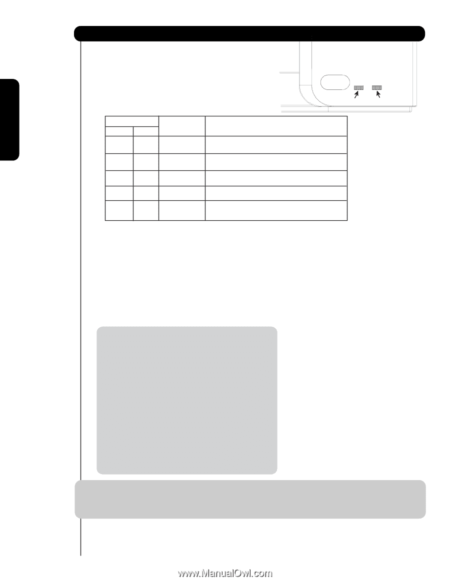
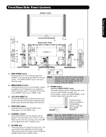
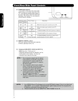
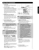
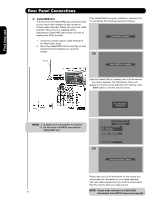
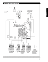
First time use Front/Rear/Side Panel Controls ቩ POWER light indicator To turn the TV ON, press the main power switch located on the lower right side of the TV. A red stand-by indicator lamp located on the lower right corner of the front bezel will illuminate. The Plasma TV is now ready for remote ON/OFF operation. Lamp 1 Lamp 2 Indicating Lamp Power Status Lamp 1 Lamp 2 Off Off OFF. Lights Red Off Off Off Blinking Blue Lights Blue Lights Orange Off OFF. (Stand-by) OFF. (Turning ON ) O n Off (Power Saving) Operating When the main power switch is set to O . When the main power switch on the TV is ON. TV MAIN POWER is ON ; but no picture is shown. TV MAIN POWER is ON ; picture is shown. TV MAIN POWER is ON with no signal input except antenna (no sync. signal). ቪ REMOTE CONTROL sensor Point your remote at this area when selecting channels, adjusting volume, etc. ቫ Component SIDE INPUT JACKS (for INPUT: 5) INPUT 5 provide Y-PBPR jacks for connecting equipment with this capability, such as a DVD player or Set Top Box. You may use composite video signal for this input. NOTE: 1. Your component outputs may be labeled Y, B-Y, and R-Y. In this case, connect the components B-Y output to the TV's PB input and the components R-Y output to the TV's PR input. 2. Your component outputs may be labeled Y-CBCR. In this case, connect the component CB output to the TV's PB input and the component CR output to the TV's PR input. 3. It may be necessary to adjust TINT to obtain optimum picture quality when using the Y-PBPR inputs (see page 37). 4. INPUT 3, INPUT 4 and INPUT 5 (Y/VIDEO) can be used for composite video and component video input. NOTES: 1. Your HITACHI Plasma TV will appear to be turned OFF (lights orange) if there is no video input when INPUT : 1, 2, 3, 4 and 5. Check the Power Light to make sure the TV is turned off or in Stand-by mode (lights red) when not in use. 2. Remote Control can not turn ON/OFF the "MAIN POWER" of the TV. 12
-
 1
1 -
2
-
3
-
4
-
5
-
6
-
 7
7 -
 8
8 -
 9
9 -
 10
10 -
 11
11 -
 12
12 -
 13
13 -
 14
14 -
 15
15 -
 16
16 -
 17
17 -
18
-
19
-
20
-
21
-
22
-
23
-
24
-
25
-
26
-
27
-
28
-
29
-
30
-
31
-
32
-
33
-
34
-
35
-
36
-
37
-
38
-
39
-
40
-
41
-
42
-
43
-
44
-
45
-
46
-
47
-
48
-
49
-
50
-
51
-
52
-
53
-
54
-
55
-
56
-
57
-
58
-
59
-
60
-
61
-
62
-
63
-
64
-
65
-
66
-
67
-
68
-
69
-
70
-
71
-
72
-
73
-
74
-
75
-
76
-
77
-
78
-
79
-
80
 |
 |