Hitachi CR13VA Instruction Manual - Page 13
Adjusting the blade reciprocating speed - reciprocating saw
 |
UPC - 717709005617
View all Hitachi CR13VA manuals
Add to My Manuals
Save this manual to your list of manuals |
Page 13 highlights
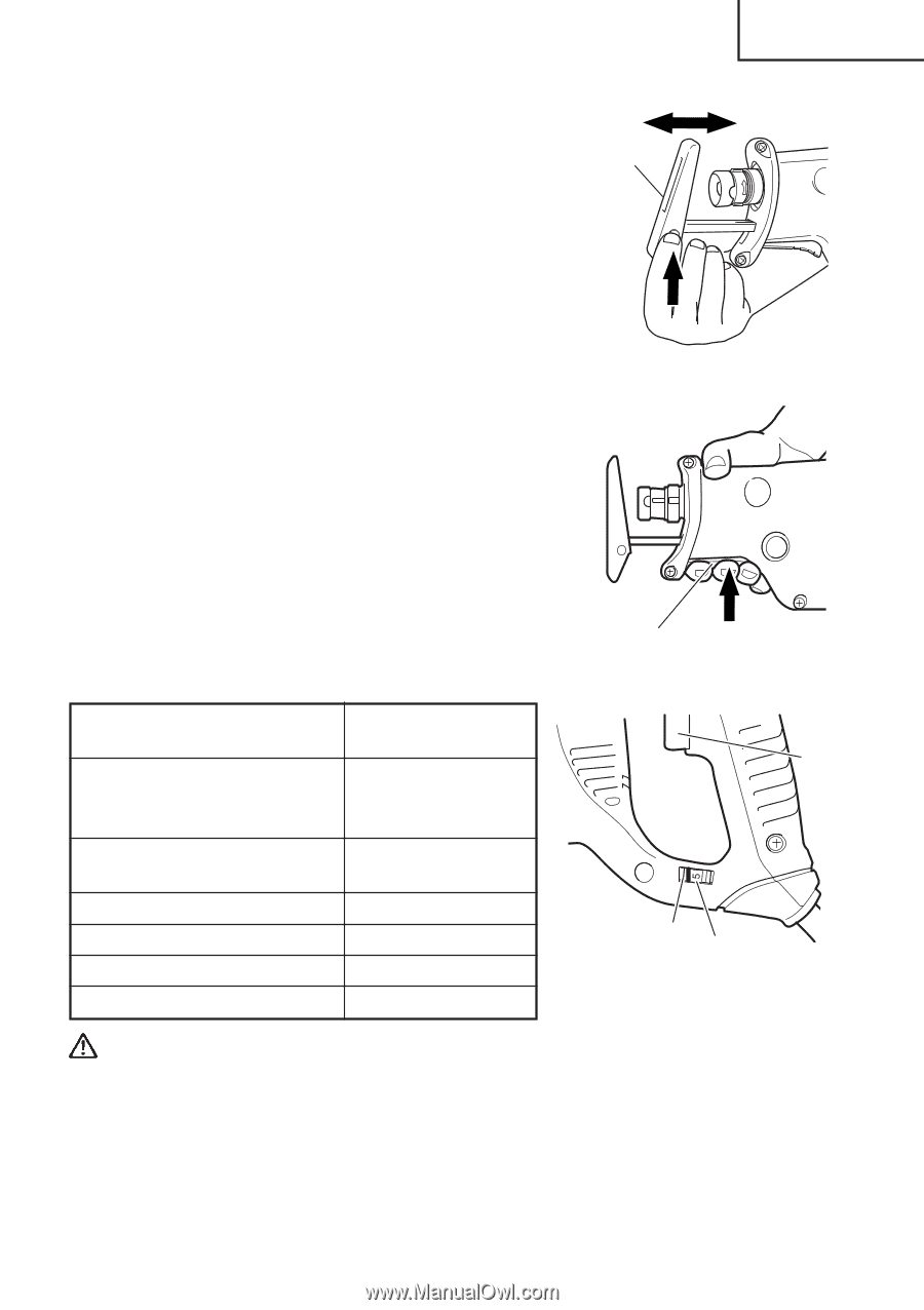
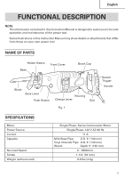
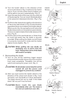
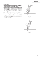
English (2) Push up the base tip and jog the base back and forth. (Fig. 11) (3) You can adjust the base position in three stages. Move the base at an interval of about 15 mm, find the position where the base hooks, and press in the base lever with your fingers. The base is secured when you hear the clicking sound. (Fig. 12) 9. Adjusting the blade reciprocating speed This unit has a built-in electronic control circuit that makes it possible to adjust the variable speed of the saw blade either both by pulling a switching trigger or turning a dial. (Fig. 13) (1) If you pull the trigger further in, the speed of the blade accelerates. Begin cutting at a low speed to ensure the accuracy of your target cut position. Once you've obtained a sufficient cutting depth, increase the cutting speed. (2) On the dial scale, "5" is the maximum speed and "1" the minimum. The high speed is generally suitable for soft materials such as wood, and the low speed is suitable for hard materials such as metal. We recommend that you use the following as a rough guide in selecting the suitable speed for the materials you are cutting. Example of materials to be cut Recommended dial scale Mild steel pipes / cast-iron tubes / L-shaped angle steel 2 - 4 Wood / wood with nails driven in 5 Stainless steel 1 - 3 Aluminum / brass / copper 2 - 4 Plaster board 4 - 5 Plastic / fiber board 1 - 3 Base Fig. 11 Base Lever Fig. 12 Dial Scale Fig. 13 Switch Trigger CAUTION: ⅜ When cutting at low speed (scale of 1 - 2), never cut a wooden board more than 25/64" (10 mm) thick or a mild steel plate more than 5/64" (2 mm) thick. The load on the motor can result in overheating and damage. ⅜ Although this unit employs a powerful motor, prolonged use at a low speed will increase the load unduly and may lead to overheating. Properly adjust the saw blade to allow steady, smooth cutting operation, avoiding any unreasonable use such as sudden stops during cutting operation. 13
-
 1
1 -
2
-
3
-
4
-
5
-
6
-
7
-
 8
8 -
 9
9 -
 10
10 -
 11
11 -
 12
12 -
 13
13 -
 14
14 -
 15
15 -
 16
16 -
 17
17 -
 18
18 -
19
-
20
-
21
-
22
-
23
-
24
-
25
-
26
-
27
-
28
-
29
-
30
-
31
-
32
-
33
-
34
-
35
-
36
-
37
-
38
-
39
-
40
-
41
-
42
-
43
-
44
-
45
-
46
-
47
-
48
-
49
-
50
-
51
-
52
-
53
-
54
-
55
-
56
-
57
-
58
-
59
-
60
 |
 |