Hitachi HTS541080G9SA00 Specifications - Page 94
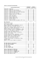
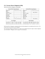
Table 46: Device Configuration Overlay Data structure, Table 47: DCO error information definition.
 |
UPC - 683728182632
View all Hitachi HTS541080G9SA00 manuals
Add to My Manuals
Save this manual to your list of manuals |
Page 94 highlights
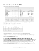
Table 46: Device Configuration Overlay Data structure Word 0 1 2 3-6 7 8 9 10 11-254 255 Content 0001h Data Structure revision Multiword DMA modes supported 15-3 Reserved 2 1 = Multiword DMA mode 2 and below are supported 1 1 = Multiword DMA mode 1 and below are supported 0 1 = Multiword DMA mode 0 is supported Ultra DMA modes supported 15-6 Reserved 5 1 = Ultra DMA mode 5 and below are supported 4 1 = Ultra DMA mode 4 and below are supported 3 1 = Ultra DMA mode 3 and below are supported 2 1 = Ultra DMA mode 2 and below are supported 1 1 = Ultra DMA mode 1 and below are supported 0 1 = Ultra DMA mode 0 is supported Maximum LBA address Command set/feature set supported 15-9 Reserved 8 1 = 48-bit Addressing feature set supported 7 Reserved 6 1 = Automatic acoustic management supported 5 Reserved 4 1 = Power-Up in Standby feature set supported 3 1 = SMART feature set supported 2 1 = SMART error log supported 1 1 = SMART sefl-test supported 0 1 = SMART feature set supported Automatic Acoustic Mode status Automatic Acoustic Mode current value SATA feature 4 1=Software setting Preservation 3 Reserved 2 1=Set interface power management 1-0 Reserved Reserved Integrity word 15-8 Checksum 7-0 Signature (A5h) Note: Bits 7-0 of this word contain the value A5h. Bits 15-8 of this word contain the data structure checksum. The data structure checksum is the two's complement of the sum of all byte in words 0through 254 and the byte consisting of bits 7-0 of word 255. Each byte is added with unsigned arithmetic, and overflow is ignored. The sum of all bytes is zero when the checksum is correct. Table 47: DCO error information definition. LBA High LBA Mid Sector count invalid word location invalid bit location (bits 7:0) error reason code & description (bits 15:8) 01h DCO feature is frozen 02h Device is now Security Locked mode 03h Device's feature is already modified with DCO Travelstar 5K100 (Serial ATA) Hard Disk Drive Specification 82
-
 1
1 -
2
-
3
-
4
-
5
-
6
-
7
-
8
-
9
-
10
-
11
-
12
-
13
-
14
-
15
-
16
-
17
-
18
-
19
-
20
-
21
-
22
-
23
-
24
-
25
-
26
-
27
-
28
-
29
-
30
-
31
-
32
-
33
-
34
-
35
-
36
-
37
-
38
-
39
-
40
-
41
-
42
-
43
-
44
-
45
-
46
-
47
-
48
-
49
-
50
-
51
-
52
-
53
-
54
-
55
-
56
-
57
-
58
-
59
-
60
-
61
-
62
-
63
-
64
-
65
-
66
-
67
-
68
-
69
-
70
-
71
-
72
-
73
-
74
-
75
-
76
-
77
-
78
-
79
-
80
-
81
-
82
-
83
-
84
-
85
-
86
-
87
-
88
-
 89
89 -
 90
90 -
 91
91 -
 92
92 -
 93
93 -
 94
94 -
 95
95 -
 96
96 -
 97
97 -
 98
98 -
 99
99 -
100
-
101
-
102
-
103
-
104
-
105
-
106
-
107
-
108
-
109
-
110
-
111
-
112
-
113
-
114
-
115
-
116
-
117
-
118
-
119
-
120
-
121
-
122
-
123
-
124
-
125
-
126
-
127
-
128
-
129
-
130
-
131
-
132
-
133
-
134
-
135
-
136
-
137
-
138
-
139
-
140
-
141
-
142
-
143
-
144
-
145
-
146
-
147
-
148
-
149
-
150
-
151
-
152
-
153
-
154
-
155
-
156
-
157
-
158
-
159
-
160
-
161
-
162
-
163
-
164
-
165
-
166
-
167
-
168
-
169
-
170
-
171
-
172
-
173
-
174
-
175
-
176
-
177
-
178
-
179
-
180
-
181
-
182
-
183
-
184
-
185
-
186
-
187
-
188
-
189
-
190
-
191
-
192
-
193
-
194
-
195
-
196
-
197
-
198
-
199
-
200
-
201
-
202
-
203
-
204
-
205
 |
 |
