Holmes HT38R Instruction Manual - Page 2
Please Read And Save, These Important, Safety Instructions
 |
View all Holmes HT38R manuals
Add to My Manuals
Save this manual to your list of manuals |
Page 2 highlights
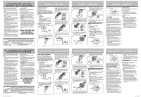
PLEASE READ AND SAVE THESE IMPORTANT SAFETY INSTRUCTIONS When using electrical appliances, basic safety precautions should always be taken including the following: 1. Read all instructions before using this appliance. 2. Use fan only for purposes described in the instruction manual. 3. To protect against electrical shock do not immerse unit, plug or cord in water or spray with liquids and plug the appliance directly into a 120V AC electrical outlet. 4. Close supervision is necessary when any appliance is used by or near children. 5. Unplug from outlet when not in use, when moving fan from one location to another, before putting on or taking off parts and before cleaning. 6. Avoid contact with moving parts. 7. Do not operate in the presence of explosive and/or flammable fumes. 8. To avoid fire hazard, NEVER place the cord under rugs or any parts near an open flame, cooking or other heating appliance. 9. Do not operate any appliance with a damaged cord or plug after the appliance malfunctions, or has been dropped/damaged in any manner. Discard fan or return to an authorized service facility for examination and/or repair. 10. Do not run cord under carpeting. Do not cover cord with throw rugs, runner, or similar coverings. Do not route cord under furniture or appliances. Arrange cord away from traffic area and where it will not be tripped over. 11. The use of attachments not recommended or sold by the appliance manufacturer may cause hazards. 12. Do not let the cord hang over the edge of a table, counter or come in contact with hot surfaces or leave exposed to high traffic areas. 13. Do not use outdoors. 14. To disconnect, grip plug and pull from wall outlet. Never yank on cord. 15. Always use on a dry, level surface. 16. Do not operate fan until fully assembled with all parts properly in place. 17. This product is intended for household use ONLY and not for commercial or industrial applications. 18. WARNING: To reduce the risk of electrical shock and injury to persons, do not use in window. 19. WARNING: To reduce the risk of fire or electric shock, do not use this fan with any solid-state speed control device. 20. This product employs overload protection (fuse). A blown fuse indicates an overload or short-circuit situation. If the fuse blows, unplug the product from the outlet. Replace the fuse as per the user servicing instructions (follow product marking for proper fuse rating) and check the product. If the replacement fuse blows, a short circuit may be present and the product should be discarded or returned to an authorized service facility for examination and/or repair. PLEASE READ AND SAVE THESE IMPORTANT SAFETY INSTRUCTIONS THIS APPLIANCE HAS A POLARIZED PLUG (one blade is wider than the other). To reduce the risk of electric shock, this plug is intended to fit in a polarized outlet only one way. If the plug does not fit fully in the outlet, reverse the plug. If it still does not fit, contact a qualified electrician to install the proper outlet. DO NOT ATTEMPT TO MODIFY THIS PLUG OR DEFEAT THIS SAFETY FEATURE IN ANY WAY. FEATURES - OPERATIONS ASSEMBLY INSTRUCTIONS Assembly Time: 10-15 minutes. Tools Required: Phillips head screw driver. NOTE: MAKE SURE YOU REMOVE ALL CONTENTS FROM THE PACKAGE. PLEASE CHECK PACKAGING MATERIALS FOR PARTS THAT COULD BE REQUIRED TO OPERATE YOUR FAN. LOCATE THE BELOW PARTS FROM THE BOX TO PREPARE FOR ASSEMBLY: • Fan housing • 2 pedestal halves • 2 base halves • 8 M4x8mm screws (4 pcs for pedestal assembly and 4 pcs for base assembly) • Cord clip with 2 M4x12mm screws (affixed underneath the base inside the package box) • Remote Control (placed in a plastic bag inside the package box) Follow the steps below in order to assemble the fan pedestal and base before operating your fan: 1. To assemble the pedestal, simply snap the 2 pedestal halves together (Fig. 1). Fig. 1 3. Align marking "A", located at the bottom of the fan housing, with marking "A" on the top end of the pedestal. Insert the alignment post from the pedestal into the alignment hole on fan housing for proper alignment (Fig. 3). Fig. 3 Alignment Hole "A" A Alignment Post "A" 4. Use 4 screws (M4x8mm) provided to attach the assembled pedestal to the bottom of the fan housing. Secure the screws with a screwdriver (Fig. 4). Fig. 4 4 screws (M4x8mm) 2. Pull the power cord through the assembled pedestal, making sure the wider end of the pedestal is facing towards the fan housing (Fig. 2). Fig. 2 5. Snap the 2 base halves together by sliding the posts of one base half into the slots of the second base half (Fig. 5). Fig. 5 FEATURES - OPERATIONS 6. Pull the power cord through the center hole of the assembled base (Fig. 6). Fig. 6 9. Wind the power cord underneath the base. Loosen the cord clip and place cord inside the clip. Secure the cord clip onto the base bottom with the 2 screws (M4x12mm) provided (Fig. 9). Fig. 9 2 screws (M4x12mm) Cord Clip 2 screws (M4x12mm) 7. Align marking "B", located at the center hole of the assembled base, with marking "B" at the bottom end of the pedestal. Insert the alignment post from the pedestal into the alignment hole on base for proper alignment (Fig. 7). Fig. 7 Alignment Post "B" B B Alignment Hole "B" 8. Use 4 screws (M4x8mm) provided to attach the assembled base to the pedestal. Secure the screws with a screwdriver (Fig. 8). Fig. 8 10. Turn fan right side up and place on a dry and level surface before operating. OPERATING INSTRUCTIONS (SEE FIG. 10, 11) A. Power/Speed Settings Press = On, I, II, III, Off B. Timer Control Press = Turns Off in 1, 2, 4, 8 hours C. Oscillation Control Press = Oscillation On, Off D. Natural Breeze, Sleep Breeze Modes Press = Natural Breeze, Sleep Breeze Natural Breeze Mode will cycle through the fan speed settings randomly. Sleep Breeze Mode will cycle through the fan speed settings in order. Fig. 10 Control Panel 4 screws (M4x8mm) A D C B FEATURES - OPERATIONS Fig. 11 Remote Control A D B C FCC STATEMENT Potential for Radio/Television interference This device complies with Part 15 of the FCC Rules. Operation is subject to the following two conditions: (1) This device may not cause harmful interference, and (2) this device must accept any interference received, including interference that may cause undesired operation. This product has been tested and found to comply with the limits for a Class B digital device, pursuant to part 15 of the FCC rules. These limits are designed to provide reasonable protection against harBmTf1u6l-UinKte8r/f0er5ence in a residential installation. The product generates, uses, and can radiate radio frequency energy and, if not installed and used in accordance with the instructions, may cause harmful interference to radio communications. However, there is no guarantee that the interference will not occur in a particular installation. If the product does cause harmful interference to radio or television reception, which can be determined by turning the product on or off, the user is encouraged to try to correct the interference by one or more of the following measures: • Reorient or relocate the receiving antenna. • Increase the separation between the product and the receiver. • Connect the product into an outlet on a circuit different from that to which the receiver is connected. • Consult the dealer or an experienced radio/TV technician for help. • Changes or modifications not expressly approved by the party responsible for compliance could void the user's authority to operate the equipment. REMOTE CONTROL This fan includes a remote control requiring two (2) AAA batteries, 1.5V (not included). Battery Replacement a) Remove battery cover from remote control. b) Remove old batteries from the remote control. c) Insert two new batteries, pressing them firmly into their slot. d) Replace the battery cover. NOTES: • Replace all batteries of a set at the same time. • Being careful not to bend or damage the contact spring, clean the battery contacts and devices' contacts prior to installing the batteries. • Remove the batteries from the equipment when it is not being used for an extended period of time. • Remove the used batteries promptly. • Do not mix old and new batteries. Do not mix alkaline, standard (carbon-zinc), or rechargeable batteries. • Do not discard used batteries into household trash containers. Contact your local government for disposal or recycling practices in your area. LEA Y CONSERVE ESTAS IMPORTANTES INSTRUCCIONES DE SEGURIDAD Cuando se usen artefactos eléctricos, siempre se deben tomar precauciones básicas de seguridad, incluyendo las siguientes: 1. Lea todas las instrucciones antes de usar este artefacto. 2. Sólo utilice el ventilador para el propósito descrito en este manual. 3. Para evitar los riesgos de choque eléctrico, no sumerja la unidad, el enchufe ni el cordón en agua ni les rocíe líquidos. Enchufe el artefacto directamente a un tomacorriente de 120 V de CA. 4. Se necesita supervisión estrecha cuando los niños usen cualquier artefacto o se usen cerca de ellos. 5. Siempre desenchufe el ventilador cuando no esté en uso, antes de moverlo a otro lugar, instalarle o quitarle piezas o limpiarlo. 6. Evite el contacto con las piezas movibles. 7. NO opere esta unidad en presencia de gases o vapores explosivos y/o inflamables. 8. Para evitar el riesgo de incendio NUNCA coloque el cordón debajo de alfombras ni parte alguna cerca de llamas abiertas, hornillas ni otros artefactos que generen calor. 9. No opere artefacto alguno con el cordón o el enchufe dañados, después de haber funcionado mal, de haberse caído o dañado de cualquier forma. Deshágase del ventilador o llévelo a un servicio técnico autorizado para su revisión o reparación. 10. No extienda el cable debajo de la alfombra. No cubra el cable con tapetes, alfombras de camino o cubiertas similares. Coloque el cable lejos del área de tráfico y donde nadie se vaya a tropezar. 11. El uso de accesorios o dispositivos no recomendados o vendidos por el fabricante puede generar riesgos. 12. No permita que el cordón cuelgue de la mesa o mostrador, que haga contacto con superficies calientes, ni lo deje expuesto en áreas de mucho tránsito. 13. No lo utilice en exteriores. 14. Para desenchufar el ventilador, jale del enchufe, nunca del cordón. 15. Siempre colocarlo sobre una superficie seca y nivelada. 16. No opere el ventilador hasta que esté totalmente ensamblado y con todas sus piezas instaladas adecuadamente en su lugar. 17. Este artefacto sólo es para uso doméstico y no para uso comercial ni industrial. 18. ADVERTENCIA: Para reducir el riesgo de descarga eléctrica o de lesiones, no lo utilice en las ventanas. 19. ADVERTENCIA: Para reducir el riesgo de incendio o choque eléctrico, no use este ventilador con ningún otro dispositivo con control de velocidad de estado sólido. 20. Este producto utiliza una protección contra la sobrecarga (fusible). Un fusible quemado indica que hubo una situación de sobrecarga o un corto circuito. Si se quema un fusible, desenchufe el producto del tomacorriente. Reemplace el fusible de acuerdo a las instrucciones de mantenimiento (hágalo de acuerdo a la marca del producto para obtener la clasificación apropiada del fusible). Si se quema el fusible de reemplazo, debe haber un corto circuito y el producto debería desecharse o llevarse a un centro de servicio técnico autorizado para que lo revisen o reparen. LEA Y CONSERVE ESTAS INSTRUCCIONES IMPORTANTES DE SEGURIDAD ESTE PRODUCTO TIENE UN ENCHUFE POLARIZADO (una hoja es más ancha que la otra). A fin de disminuir el riesgo de descarga eléctrica, este enchufe está diseñado para insertarse en un tomacorriente polarizado en un solo sentido. Si el enchufe no entra completamente en el tomacorriente, inviértalo. Si aun así no entra, llame a un electricista calificado para instalar un tomacorriente apropiado. NO MODIFIQUE EL ENCHUFE NI ANULE ESTA FUNCION DE SEGURIDAD DE NINGUNA MANERA. HT38R_HTF3610AR_15ESM1.indd 2 CARACTERISTICA - FUNCIONAMIENTO INSTRUCCIONES DE ENSAMBLADO Tiempo de ensamblado: De 10 a 15 minutos. Herramientas requeridas. Destornillador de estrella NOTA: ASEGÚRESE DE EXTRAER TODO EL CONTENIDO DEL EMBALAJE. COMPRUEBE QUE EN EMBALAJE ESTÁN TODAS LAS PIEZAS NECESARIAS PARA QUE SU VENTILADOR FUNCIONE. UBIQUE LAS PARTES A CONTINUACIÓN EN LA CAJA A FIN DE PREPARAR EL ENSAMBLE: • Cubierta del ventilador • 2 mitades del pedestal • 2 mitades de base • 8 tornillos M4x8mm (4 piezas para el ensamble del pedestal y 4 piezas para el ensamble de la base) • Sujetador del cable con 2 tornillos M4x12mm (fijados debajo de la base en el interior de la caja del envase) • Control remoto (ubicado en una bolsa de plástico en el interior de la caja del envase) Siga los siguientes pasos para ensamblar el pedestal y la base del ventilador antes de ponerlo en funcionamiento: 1. Para armar el pedestal, simplemente abroche las 2 mitades del pedestal juntas (Fig. 1). 3. Alinee la marca "A" ubicada en la parte inferior de la cubierta del ventilador, la marca "A" debe estar en la parte superior del pedestal. Inserte el palo de alineación del pedestal en el orificio de alineación sobre la cubierta del ventilador para una alineación adecuada (Fig. 3). Fig. 3 Alineación del orificio "A" A Alineación del palo "A" 4. Use los 4 tornillos (M4x8mm) provistos para fijar el pedestal ensamblado en la parte inferior de la cubierta del ventilador. Fije los tornillos con un destornillador (Fig. 4). Fig. 4 Fig. 1 4 tornillos (M4x8mm) 2. Tire el cable de alimentación a través del pedestal ensamblado, asegurándose de que el extremo más ancho del pedestal mire hacia la cubierta del ventilador (Fig. 2). Fig. 2 5. Calce las 2 mitades de las bases juntas deslizando los palos de una mitad de la base en las ranuras de la segunda mitad de la base (Fig. 5). Fig. 5 CARACTERISTICA - FUNCIONAMIENTO 6. Tire el cable de alimentación a través del orificio central de la base ensamblada (Fig. 6). Fig. 6 inferior de la base con los 2 tornillos (M4x12mm) provistos (Fig. 9). Fig. 9 2 tornillos (M4x12mm) Sujetador del cable 2 tornillos (M4x12mm) 7. Alinee la marca "B", ubicada en el orificio central de la base ensamblada, con la marca "B" en el extremo inferior del pedestal. Inserte el palo de alineación del pedestal en el orificio de alineación de la base para una alineación adecuada (Fig. 7). Fig. 7 Alineación del palo "B" B B Alineación del orificio "B" 8. Utilice los 4 tornillos (M4x8mm) provistos para fijar la base ensamblada al pedestal. Fije los tornillos con un destornillador (Fig. 8). Fig. 8 10. Gire la parte derecha del ventilador hacia arriba y colóquelo sobre una superficie seca y nivelada antes de hacerlo funcionar. INSTRUCCIONES DE USO (VER FIG. 10, 11) A. Configuración de encendido y de velocidades Presione = encendido, I, II, III, apagado B. Control de temporizador Presione = apagado automático en 1, 2, 4, 8 horas C. Control de oscilación Presione = encendido y apagado de oscilación D. Modos Brisa natural y Brisa para dormir Presione = Brisa natural, Brisa para dormir El modo Brisa natura recorrerá al azar todas las configuraciones de velocidad. El modo Brisa para dormir recorrerá en orden todas las configuraciones de velocidad. Fig. 10 Panel de control 4 tornillos (M4x8mm) A 9. Enrosque el cable de alimentación debajo de la base. Afloje el sujetador del cable y coloque el cable dentro del sujetador. Fije el sujetador del cable en la parte D C B CARACTERISTICA - FUNCIONAMIENTO Fig. 11 Control Remoto A • Pedir ayuda al distribuidor o a un técnico de radio/ TV idóneo. • Todo cambio o modificación que no haya sido expresamente autorizado por la parte responsable de D exigir el cumplimiento podría anular la autoridad del usuario para usar el equipo. B C DECLARACIÓN DE LA COMISIÓN FEDERAL DE COMUNICACIONES (FCC POR SUS SIGLAS EN INGLÉS) Posibilidad de interferencias con Radio/ Televisión Este equipo cumple con la Parte 15 de las Normas de la FCC. Su funcionamiento está sujeto a las siguientes dos condiciones: (1) Este equipo no puede causar interferencia perjudicial y (2) este equipo debe aceptar toda interferencia recibida, inclusive interferencia que pueda causar un funcBioTn1a6m-UieKn8to/0n5o deseado. Este producto ha sido probado y se determinó que cumple con los límites para un dispositivo digital Clase B, según la parte 15 del reglamento de la FCC. Estos límites están diseñados para brindar protección razonable contra interferencias nocivas en una instalación residencial. El producto genera, usa y puede irradiar energía de radiofrecuencia, y si no se lo instala y se lo usa según las instrucciones, puede causar interferencias adversas en las comunicaciones radiales. Sin embargo, no hay garantía de que la interferencia no ocurra en una instalación en particular. Si el producto causa interferencias nocivas en la recepción de radio o televisión, lo cual se puede determinar apagando y encendiendo el producto, se recomienda al usuario que intente corregir la interferencia por medio de una de los siguientes métodos: • Reorientar o reubicar la antena receptora. • Aumentar la separación entre el producto y el receptor. • Conectar el producto a una salida en un circuito diferente de aquella a la cual está conectado el receptor. CONTROL REMOTO Este ventilador incluye un control remoto que requiere dos (2) baterías AAA , 1.5V (no incluidas). Reemplazo De Pilas a) Retire la cubierta de las pilas del control remoto. b) Retire las pilas antiguas del control remoto. c) Inserte dos nuevas pilas y presiónelas firmemente hacia adentro de la cavidad. d) Vuelva a colocar la cubierta de las pilas. NOTAS: • Reemplace todas las pilas al mismo tiempo. • Con cuidado de no doblar ni dañar el resorte de contacto, limpie los contactos de la batería y los contactos de los dispositivos antes de instalar las baterías. • Quite las pilas del equipo cuando no lo vaya a usar por un período de tiempo prolongado. • Reemplace las pilas que estén agotadas. • No mezcle pilas nuevas y viejas. No mezcle pilas alcalinas, comunes (carbón-zinc) o recargables. • No deseche las baterías usadas en contenedores de basura de la casa. Comuníquese con el gobierno local para informarse sobre las prácticas de reciclaje o de desecho de su zona. 3/5/15 8:49 AM
-
 1
1 -
 2
2
 |
 |
