Homelite HG5000 Replacement Parts List - Page 13

Parts List For D - engine

Page 13 highlights

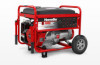
HOMELITE GENERATOR − HG5000 SERIES The model number will be found on a label attached to the frame. Always mention the model number in all correspondence regarding your GENERATOR or when ordering replacement parts. PARTS LIST FOR FIGURE D KEY NO. 1 2 3 4 5 6 7 8 9 10 11 12 13 14 PART NUMBER 310224016 570425001 661505010 638326003 678355005 570371004 310222013 570356004 638706007 678457007 570355003 678522010 310223004 620599012 DESCRIPTION QTY. Handle Bar Assembly (Incl. Key No. 6 2 Handle Bar Plug 2 Bolt (M8 x 45 mm 2 Handle Bar Insert 4 Nut (M8 5 Handle Grip 2 Frame 1 Motor Mount 4 Foot, Bracket 2 Nut (M10 8 Rubber Foot 2 Cotter Pin (3 mm 2 Wheel (10 in 2 Axle 2 KEY PART NO. NUMBER DESCRIPTION QTY. 15 678833001 Nut (M12, Flange Hd 2 16 678610004 Flange Nut (M6 2 17 660972008 Screw (M6 x 25 2 18 310227019 Generator Head Assembly (Incl. Key Nos. 1-10 1 19 940678132 Data Label 1 20 940513017 Ground Label 1 21 099958001600 Engine 1 22 941494003 Fuel Valve Label 1 23 940654088 Combustion Label 1 24 940680034 Hot Surface Warning Label 2 25 940974007 Fire Danger Label 1 26 940513001 Ground Warning Label 1 27 940708007 Lubricant Label 1 WARNING: To avoid possible personal injury or equipment damage, a registered electrician or an authorized service representative should perform installation and all service. Under no circumstances should an unqualified person attempt to wire into a utility circuit. 13

  • 1
  • 2
  • 3
  • 4
  • 5
  • 6
  • 7
  • 8
  • 9
  • 10
  • 11
  • 12
  • 13
  • 14
  • 15
  • 16
  • 17
  • 18
  • 19
  • 20
  • 21
  • 22
  • 23
  • 24
  • 25
  • 26
  • 27
  • 28
  • 29
  • 30
  • 31
  • 32

13
HOMELITE GENERATOR − HG5000 SERIES
PARTS LIST FOR FIGURE D
The model number will be found on a label attached to the frame. Always mention the model number in all correspondence regarding your
GENERATOR
or when ordering replacement parts.
WARNING:
To avoid possible personal injury or equipment damage, a registered electrician or an authorized service representative should perform installation and all service. Under no circumstances should an
unqualified person attempt to wire into a utility circuit.
1
310224016
Handle Bar Assembly (Incl. Key No. 6)
.....................................
2
2
570425001
Handle Bar Plug
.......................................................................
2
3
661505010
Bolt (M8 x 45 mm)
....................................................................
2
4
638326003
Handle Bar Insert
......................................................................
4
5
678355005
Nut (M8)
....................................................................................
5
6
570371004
Handle Grip
..............................................................................
2
7
310222013
Frame
.......................................................................................
1
8
570356004
Motor Mount
.............................................................................
4
9
638706007
Foot, Bracket
............................................................................
2
10
678457007
Nut (M10)
..................................................................................
8
11
570355003
Rubber Foot
.............................................................................
2
12
678522010
Cotter Pin (3 mm)
.....................................................................
2
13
310223004
Wheel (10 in.)
............................................................................
2
14
620599012
Axle
..........................................................................................
2
KEY
PART
NO.
NUMBER
DESCRIPTION
QTY.
KEY
PART
NO.
NUMBER
DESCRIPTION
QTY.
15
678833001
Nut (M12, Flange Hd.)
..............................................................
2
16
678610004
Flange Nut (M6)
........................................................................
2
17
660972008
Screw (M6 x 25)
........................................................................
2
18
310227019
Generator Head Assembly (Incl. Key Nos. 1-10)
......................
1
19
940678132
Data Label
................................................................................
1
20
940513017
Ground Label
............................................................................
1
21 099958001600 Engine
.......................................................................................
1
22
941494003
Fuel Valve Label
.......................................................................
1
23
940654088
Combustion Label
....................................................................
1
24
940680034
Hot Surface Warning Label
......................................................
2
25
940974007
Fire Danger Label
.....................................................................
1
26
940513001
Ground Warning Label
.............................................................
1
27
940708007
Lubricant Label
.........................................................................
1