Homelite UT10568 User Manual - Page 26
Replacing The Guide Bar And, Chain, Danger, Warning
 |
View all Homelite UT10568 manuals
Add to My Manuals
Save this manual to your list of manuals |
Page 26 highlights
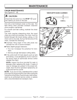
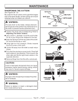
MAINTENANCE REPLACING THE GUIDE BAR AND CHAIN See Figures 34 - 43. DANGER: Never start the engine before installing the guide bar, chain, clutch cover, and clutch drum. Without all these parts in place, the clutch can fly off or explode, exposing the user to possible serious injury. CUTTERS CHAIN ROTATION CHAIN DRIVE LINKS WARNING: To avoid serious personal injury, read and understand all the safety instructions in this section. n Always place the switch in the STOP " " position before you work on the saw. n Make sure the chain brake is not set by pulling the chain brake lever/hand guard towards the front handle to the run position. NOTE: When replacing the guide bar and chain, always use the specified bar and chain listed in the Bar and Chain Combinations section later in this manual. n Wear gloves when handling the chain and bar. These components are sharp and may contain burrs. n Remove the bar mounting nuts using the combination wrench provided. n Remove the clutch cover. n Remove the bar and chain from the mounting surface. n Remove the old chain from the bar. n Lay out the new saw chain in a loop and straighten any kinks. The cutters should face in the direction of chain rotation. If they face backwards, turn the loop over. n Place the chain drive links into the bar groove as shown. n Position the chain so there is a loop at the back of the bar. n Hold the chain in position on the bar and place the loop around the sprocket. Fig. 37 BAR GROOVE CHAIN DRIVE LINKS Fig. 38 n Fit the bar flush against the mounting surface so that the bar studs are in the long slot of the bar. n Replace the clutch cover ensuring that the adjusting pin in the clutch cover is in the bar chain tensioning pin hole and that both bar studs are securely in their respective holes in the clutch cover. NOTE: The adjusting pin may need to be slightly repositioned with the chain tensioning screw Page 26 - English
-
 1
1 -
2
-
3
-
4
-
5
-
6
-
7
-
8
-
9
-
10
-
11
-
12
-
13
-
14
-
15
-
16
-
17
-
18
-
19
-
20
-
 21
21 -
 22
22 -
 23
23 -
 24
24 -
 25
25 -
 26
26 -
 27
27 -
 28
28 -
 29
29 -
 30
30 -
 31
31 -
32
-
33
-
34
-
35
-
36
-
37
-
38
-
39
-
40
-
41
-
42
-
43
-
44
-
45
-
46
-
47
-
48
-
49
-
50
-
51
-
52
-
53
-
54
-
55
-
56
-
57
-
58
-
59
-
60
-
61
-
62
-
63
-
64
-
65
-
66
-
67
-
68
-
69
-
70
-
71
-
72
-
73
-
74
-
75
-
76
-
77
-
78
-
79
-
80
-
81
-
82
-
83
-
84
-
85
-
86
-
87
-
88
-
89
-
90
-
91
-
92
-
93
-
94
-
95
-
96
-
97
-
98
-
99
-
100
-
101
-
102
-
103
-
104
-
105
-
106
-
107
-
108
-
109
-
110
-
111
-
112
-
113
-
114
-
115
-
116
-
117
-
118
-
119
-
120
 |
 |
