Homelite UT80522A User Manual - Page 12
Assembly
 |
View all Homelite UT80522A manuals
Add to My Manuals
Save this manual to your list of manuals |
Page 12 highlights
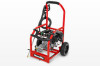
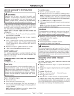
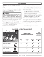
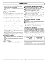
ASSEMBLY UNPACKING This product requires assembly. n Carefully remove the product and any accessories from the box. Make sure that all items listed in the packing list are included. NOTE: This tool is heavy. To avoid back injury, lift with your legs, not your back, and get help when needed. WARNING: Do not attempt to modify this tool or create accessories not recommended for use with this tool. Any such alteration or modification is misuse and could result in a hazardous condition leading to possible serious personal injury. WARNING: Do not use this product if any parts on the Packing List are already assembled to your product when you unpack it. Parts on this list are not assembled to the product by the manufacturer and require customer installation. Use of a product that may have been improperly assembled could result in serious personal injury. n Inspect the tool carefully to make sure no breakage or damage occurred during shipping. n Do not discard the packing material until you have carefully inspected and satisfactorily operated the tool. n If any parts are damaged or missing, please call 1-800-242-4672 for assistance. PACKING LIST Pressure Washer 25 ft. High Pressure Hose Trigger Handle Spray Wand Quick-connect Nozzles (4) Upper Spray Wand Holder Lower Spray Wand Holder Lock Nut M8 10 mm Bolt M8 13 mm Flange Nut 4-Cycle Engine Lubricant (SAE 30 or SAE 10W30)) Disposable Funnel Axle (2) Hitch pins (2) Wheels (2) Washers (2) Handle Operator's Manual WARNING: If any parts are damaged or missing do not operate this tool until the parts are replaced. Use of this product with damaged or missing parts could result in serious personal injury. WARNING: To prevent accidental starting that could cause serious personal injury, always disconnect the engine spark plug wire from the spark plug when assembling parts. TOOLS NEEDED See Figure 1a. n 13 mm Socket Wrench (9/16 in.) n 10 mm Wrench (7/16 in.) ATTACHING THE WHEEL ASSEMBLY See Figure 2. n Locate the axle, hitch pins, washers, and wheels. n Slide the axle through the hole in the center of the wheel. n Slide the washer onto the axle. n Lift the machine and slide the axle into the wheel mount- ing hole in the machine base as shown. n Push the hitch pin into the hole on the end of the axle to secure the wheel assembly. NOTE: The hitch pin should be pushed into the axle until the center of the pin rests on top of the axle. n Repeat with the second wheel. INSTALLING THE HANDLE See Figure 3. Push and hold the push-pin button on the side of the handle as you slide the handle onto the frame. NOTE: Before use, pull the handle up until the lock button snaps through the locking slots to secure the handle in place. INSTALLING THE UPPER AND LOWER SPRAY WAND HOLDER See Figure 4. n Align upper spray wand holder with holes in handle, as shown. n Slide long side of spray wand holder through handle and tighten securely with lock nut. n Place lower spray wand holder over the holes. n Align the bolt with the holes and push the bolt through. n Hold flange nut with 13 mm wrench and bolt head with 10 mm socket. Tighten until the bolt is snug. Page 8 - English
-
 1
1 -
2
-
3
-
4
-
5
-
6
-
 7
7 -
 8
8 -
 9
9 -
 10
10 -
 11
11 -
 12
12 -
 13
13 -
 14
14 -
 15
15 -
 16
16 -
 17
17 -
18
-
19
-
20
-
21
-
22
-
23
-
24
-
25
-
26
-
27
-
28
-
29
-
30
-
31
-
32
-
33
-
34
-
35
-
36
-
37
-
38
-
39
-
40
-
41
-
42
-
43
-
44
-
45
-
46
-
47
-
48
-
49
-
50
-
51
-
52
-
53
-
54
-
55
-
56
-
57
-
58
-
59
-
60
 |
 |
