Honeywell 4204 Installation Instructions - Page 1
Honeywell 4204 - Ademco/ Relay Module Manual
 |
UPC - 781410000834
View all Honeywell 4204 manuals
Add to My Manuals
Save this manual to your list of manuals |
Page 1 highlights
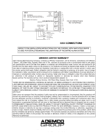
N8909 9/97 ¨ No. 4204 RELAY MODULE For Use With Control/Communicators Supporting Relay Module Connection Via Keypad Lines INSTALLATION INSTRUCTIONS GENERAL INFORMATION The 4204 Relay Module adds from one to four dry, form C (SPDT) relay outputs to compatible control/communicators. It interfaces to the controlÕs keypad wiring. The 4204 can be mounted inside the controlÕs cabinet or mounted remotely. If mounted remotely, the 4204 has two forms of protection. First, the 4204 has a built-in tamper switch which allows it to detect and report the removal of its cover to the control. Second, communication to the 4204 is supervised so that it cannot be disconnected from the keypad wiring without detection by the control. If the wiring is cut, a tamper or alarm signal will result, to indicate that this device (and possibly other devices connected to the keypad wiring) has become inoperative. INSTALLATION For UL Installations: When used with controls which do not support cover tamper or supervise communications wiring to the 4204, mount the 4204 inside the controlÕs cabinet. When used with controls which support cover tamper and supervise communications wiring to the 4204, the 4204 may either be mounted inside the controlÕs cabinet or mounted remotely. When mounted inside the control's cabinet, some controls allow the 4204 to be mounted horizontally as follows: insert the self-tapping screws (provided) in two adjacent raised tabs on the back of the cabinet. Leave the heads projecting 1/8Ó. Hang the 4204 on the screw heads via two of the slotted holes on the back of its housing. The 4204Õs cover need not, in this case, be tamper-protected. If the DIP switch is set with its position 1 ÒONÓ (see the table below), the cover can be left off. See the control's instructions for additional information. When the 4204 is mounted remotely, holes on its back permit it to be mounted horizontally or vertically. Wires can exit from the side or via the breakout on the back of its housing. The DIP switch must be set with its position 1 ÒOFFÓ and when the installation is completed, the unitÕs tamper-protected cover must be replaced. Affix the connections label that accompanies the 4204 to the inside of the 4204's cover (if the cover is used) or to the inside of the control's cover. CONNECTIONS AND SETTINGS Select and set an address for the 4204, using its DIP switch as shown in the table below. Each 4204 used with the control must be assigned a unique address so the control can identify the 4204 and communicate with it properly. The address to be set is determined by the particular control to be used, and the control's installation instructions must be consulted. As shipped, the DIP switch is set for an address of Ò0Ó. Connections to the 4204's four relays are made via 12-position terminal block TB2. Refer to the controlÕs installation instructions for specific information on how to program the controlÕs various activation options for the relays. Connections to the control's keypad wiring points can be made via 4-position terminal block TB1, the 4-pin plug, or both (wire color connections are the same). See the diagram on the other side of this page. SPECIFICATIONS Physical 6-7/16Ó W x 4-1/4Ó H x 1-1/4Ó D (163mm x 108mm x 32mm) Electrical Input Voltage: 12VDC nominal (10Ð14VDC), from controlÕs remote keypad connection points Input Current: 15mA standby + 40mA per active relay Contact Rating: 2A max. at 28VDC/AC (resistive loads) DIP SWITCH SETTINGS © ON 12 3 4 5 v v © © © © © OFF © ON SWITCH POSITION 4204 ADDRESS SETTINGS ("Ñ" means "OFF") 0 1 2 3 4 5 6 7 8 9 10 11 12 13 14 15 { 2 ON Ñ ON Ñ ON Ñ ON Ñ ON Ñ ON Ñ ON Ñ ON Ñ 3 ON ON Ñ Ñ ON ON Ñ Ñ ON ON Ñ Ñ ON ON Ñ Ñ 4 ON ON ON ON ON ON ON ON Ñ Ñ Ñ Ñ 5 ON ON ON ON ON ON ON ON v DIP SWITCH: (WHITE AREAS DENOTE SWITCH HANDLES) POSITIONS 2-5: DETERMINE 4204's ADDRESS. CONSULT CONTROLÕS INSTRUCTIONS FOR ADDRESS TO USE. SHOWN SET (AS SHIPPED) FOR ADDRESS = 0. POSITION 1: DETERMINES COVER TAMPER RESPONSE. ON = DISABLED (SHOWN, AS SHIPPED) OFF = ENABLED (COVER IS TAMPER-PROTECTED)
-
 1
1 -
 2
2
 |
 |