Honeywell 5881L Installation Instructions - Page 2
To The Installer - installation
 |
UPC - 781410331129
View all Honeywell 5881L manuals
Add to My Manuals
Save this manual to your list of manuals |
Page 2 highlights
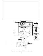
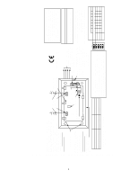
h. Do the same with the other ground lug and antenna block. i. Insert the receiver's two antennas through the two openings in the top of the cabinet, one into each block's right-hand terminal, and tighten the screws to secure them. j. Affix the receiver's Summary of Connections label to the inside of the control's cabinet door. k. Discard the receiver's unused plastic cover and base. 3. If the receiver is to be located remotely from the control in its own plastic enclosure (not in a cabinet): The circuit board mounting clips, grounding lugs and screws included with the receiver will not be needed. a. If concealed wiring is to be used, route it through the rectangular opening at the rear of the base before mounting. For surface wiring entry, a thin breakaway area is provided along the base's right edge. b. Mount the receiver in the selected location. For greatest security, use all four mounting holes (two keyslot holes and two round holes) provided in the plastic base. c Affix the receiver's Summary of Connections label to the inside of the housing cover. 4. Mounting the 5881EH in a Separate Cabinet For Commercial Fire Applications. For commercial fire applications, the 5881EH must be mounted in a separate cabinet, part # N4868V4-BE, using the Ademco Cam Lock, Part #N6277, and Retainer Clip, Part # N6277-1. Refer to the control's instructions for installing the Cam Lock and Retainer Clip in a cabinet. The cabinet containing the receiver must be located no farther than 20 feet from the alarm control cabinet., with no intervening walls or barriers): a. Remove the receiver's cover by inserting and twisting a screwdriver blade in the slot at the center of the cover's lower edge. b. Remove the receiver's circuit board from its base by bending back the two flexible plastic tabs that hold the board's lower edge. c. Mount the receiver board in the cabinet as follows: Insert the top of the receiver board into the supporting slots provided at the top of the cabinet (see Diagram 1 and Detail A which show how the top of the receiver board is secured). Secure the bottom of the receiver board with 2 screws (not supplied) using an insulating washer between the head of each mounting screw and the PC board. d. Affix the receiver's Summary of Connections label to the inside of the cabinet door. e. Discard the receiver's unused plastic cover and base. 5. Setting The DIP switches (All Receivers): Set the receiver's DIP switch to identify the receiver's address (refer to the DIP switch chart in Diagram 2). 5881EH Only: DIP switch #5 is used on the 5881EH, as follows: For commercial fire applications, DIP switch #5 MUST be in the ON position. Note: All other system components, including the control, must be approved for use in commercial fire applications. When the 5881EH is not used in a commercial fire application, switch #5 should be placed in the OFF position. 6. Insert the wiring plug (with 4 flying leads) into the mating socket on the receiver (see Diagram 2 for socket location). Connect the 4 wires to the control's corresponding remote keypad connection points (see "Interface Wiring" in the SPECIFICATIONS section). 7. Install the antennas in the right-hand terminals of the two terminal blocks at the upper edge of the circuit board, one into each block's right-hand terminal, and tighten the screws to secure them. If the receiver is mounted in a cabinet, insert the antennas through the holes in the cabinet's top first, and then into the terminal blocks. Important! If the receiver is mounted in a separate cabinet in a commercial fire installation do not use the antenna grounding lugs. 8. Replace the receiver's cover if the receiver is not mounted within a cabinet. 9. Proceed with any programming of the control that may be necessary for RF operation, and the installation of the system's wire less transmitters, as described in the QED control's installation in structions. 10. The LED located on the receiver's circuit board should be used as an indicator of strong local radio frequency interference. If this LED is continuously illuminated, the receiver should be relocated. SPECIFICATIONS Dimensions: 7-3/8" W x 4-3/8" (10-7/8" w/antennas) H x 1-7/16" D. 188mm W x 112mm H (277mm w/antennas) x 37mm D. Input Voltage: 12VDC (from QED control's remote keypad terminals). Current: 4281/4281CN: 35mA. 5881/5882: 60mA. Interface Wiring: RED 12VDC input (+) Aux Power GREEN: Data Out to Control YELLOW: Data In from Control BLACK: Ground (-) Operating Temperature: 0-50°C Range: 200ft (60m) nominal indoors from wireless transmitters (the actual range to be determined with the security system in the TEST mode). TO THE INSTALLER Regular maintenance and inspection (at least annually) by the installer and frequent testing by the user are vital to con tinuous satisfactory operation of any alarm system. The installer should assume the responsibility of developing and offering a regular maintenance program to the user, as well as ac quainting the user with the proper op eration and limitations of the alarm system and its component parts. Recommendations must be included for a specific program of frequent testing (at least weekly) to insure the system's operation at all times. 2
-
 1
1 -
 2
2 -
 3
3 -
 4
4 -
 5
5 -
 6
6 -
 7
7
 |
 |