Honeywell 5897-35 Installation Instructions - Page 2
Fcc Notice
 |
View all Honeywell 5897-35 manuals
Add to My Manuals
Save this manual to your list of manuals |
Page 2 highlights
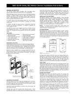
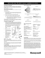
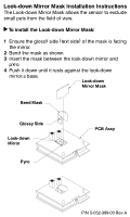
5897-35 RF DUAL TEC Motion Sensor Installation Instructions MICROWAVE SUPERVISION If the microwave technology stops sending or receiving signals, the sensor will lock into an alarm. The LEDs at the sensor, however, will not light. If the microwave regains its signal, the sensor will return to normal operation. 5897 SYSTEM PROGRAMMING The 5897-35 DUAL TEC sensor must be enrolled into the system during installation. To program the device: 1. Activate the test mode of the sensor by removing the front cover and re-installing it. (This will send a tamper signal and then a restoral to the receiver.) 2. Put the Control Panel into Zone Programming mode. 3. When you are prompted for the device serial number, either: a) Enter the 7-digit serial number through the keypad, or b) Wave your hand in front of the 5897-35 to cause an alarm, then repeat approximately 5 seconds later. (This causes a Fault and Restoral to be sent twice.) The device should now be enrolled; you may return the system to normal operation. To confirm proper sensor operation, perform the Walk-Test described on the previous page. CHANGING THE FRESNEL LENS 1. Open the cover and remove the printed circuit board (PCB). To remove the PCB, use a small-blade screwdriver and push down on the latch at the top of the front housing. Gently pull the PCB forward holding the board by the battery holder (see Figure 1). 2. Depress the retainer latch, and pull the lens retainer forward. (If necessary, use a small screwdriver to carefully depress the latch. Avoid excessive force, or the latch will Figure 3 break.) 5897-35 3. Remove the existing lens. 4. Insert the pins of the new lens into the holes on the lens retainer as shown. 5. Replace the lens and retainer together (the feet of the retainer fit into the look-down window groove). Lens Change Assembly Lens Pins LENS Retainer Latch 6. Snap the retainer latch back in place. Look-Down 7. Reassemble the Window LENS housing. NOTE: Two additional RETAINER Retainer Feet lenses are provided with the sensor. The pet-alley lens blocks lower PIR zones to exclude pets from the field of view; the barrier lens blocks outer zones for narrow applications. When the pet-alley lens is used, install a look-down mask (provided) over the inside of the look-down window, and make sure to mount the sensor at a height of 4'. UL COMPLIANCE This device is compliant to UL639 Standard for Intrusion Detection Devices, when operating within the requirements as specified for the Listed RF Receiver/Interface Board Products and appropriately Listed Burglary Control Panel Systems or Combination Burglary and Fire Warning Control Panel Systems. Refer to Figure 1 to install #4, 5/16-in. screw (supplied) as shown. NOTE: The Pet Alley feature has not been evaluated by UL. NOTE: Only one transmitting device per zone. PROTECTION PATTERNS TOP VIEW Wide Angle Lens SIDE VIEW Wide Angle Lens 7'6" floor 30' Zones Down Intermediate Long Range Lower 35' PROTECTION PATTERNS FOR SPECIAL PURPOSE LENSES TOP VIEW Barrier Lens SIDE VIEW Barrier Lens 7'6" 11' floor 35' TOP VIEW Pet-Alley Lens TheTop View Pet-Alley Lens is the same as the Top View Wide Angle Lens. 4' 35' SIDE VIEW Pet-Alley Lens 35' 5897-35 SPECIFICATIONS Range: 35' x 30' (11 m x 9 m) PIR fields of view (standard lens): 11 long range 7 intermediate 4 lower 2 look-down Power requirements: Four 3V Batteries (included). Replace Batteries only with HONEYWELL #466, Panasonic CR123A, Varta CR-123A, Duracell DL123A, or Sanyo CR123A (Lithium Manganese Dioxide) Sensitivity: 2 - 4 steps within field of view Dimensions: 5" H x 2-7/8" W x 2-5/16" D (13 cm x 7 cm x 6 cm) RFI immunity: 30 V/m, all mobile bands 10MHz 1000MHz PIR white light immunity: 4,000 Lux Weight: 10 oz (283.5 g), without batteries Operating temperature: 32° to 140° F (0° to 60° C) Frequencies: center band 2.45 GHz (microwave); 345 MHz (transmitter) Approvals / Listings: cULus Listed FCC Certified (FCC Part 15) IC Certified (RSS-210) FCC NOTICE This device complies with Part 15 of the FCC Rules. Operation is subject to the following two conditions: (1) This device may not cause harmful interference, and (2) this device must accept any interference received, including interference that may cause undesired operation. This equipment has been tested and found to comply with the limits for a field disturbance sensor, pursuant to Part 15 of the FCC Rules. The user is cautioned that changes or modifications not expressly approved by Honeywell International Inc. could void the user's authority to operate this equipment. NOTE: This equipment has been tested and found to comply with the limits for a Class B digital device, pursuant to Part 15 of the FCC Rules. These limits are designed to provide reasonable protection against harmful interference in a residential installation. This equipment generates, uses, and can radiate radio frequency energy and, if not installed and used in accordance with these instructions, may cause harmful interference to radio communications. However, there is no guarantee that interference will not occur in a particular installation. If this equipment does cause harmful interference to radio or television reception, which can be determined by turning the equipment off and on, the user is encouraged to try to correct the interference by one or more of the following measures: 1) Reorient or relocate the receiving antenna; 2) increase the separation between the equipment and the receiver; 3) connect the equipment into an outlet on a circuit different than that to which the receiver is connected; 4) consult the dealer or an experienced radio/TV technician for help. Copyright 2002 Honeywell International Inc. Honeywell and DUAL TEC® are registered trademarks of Honeywell International Inc. All other trademarks are property of their respective owners. P/N 5-051-667-00 Rev. C
-
 1
1 -
 2
2 -
 3
3
 |
 |
