Honeywell 6160RF Setup Guide - Page 1
Honeywell 6160RF Manual
 |
View all Honeywell 6160RF manuals
Add to My Manuals
Save this manual to your list of manuals |
Page 1 highlights
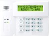
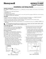
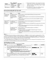
K0903V1 2/06 Rev. B ADEMCO 6160RF Keypad/Transceiver Installation and Setup Guide GENERAL INFORMATION The ADEMCO 6160RF keypad/transceiver is a combination unit that combines the functions of the following devices: • 6160 Alphanumeric Addressable Keypad • 5881H RF Receiver • 5800TM Transmitter Module The 6160RF Keypad/Transceiver may be used on any control panel that supports 5800 Series wireless devices (e.g., VISTA-10P, VISTA-15P, VISTA-20P). FEATURES • Supports wireless key transmitters (e.g.; 5804) and bi-directional transmitters (e.g.; 5804BD, 5828/5828V). • Supports wireless keys with high-security (encryption) capability (e.g.; 5804E). • Provides a nominal range of 200 feet' for RF transmitters (some transmitters have a shorter range). • Supports RF jam detection when the receiver is enabled. • Capable of sending status signals (Armed, Ready, etc.) to bi-directional units such as 5804BD, 5804BDV and 5828/5828V. UL The following 5800 series transmitters are not intended for use in UL installations: 5802, 5804, 5804BD, 5804BDV, 5804E, 5814, 5816TEMP, 5819, 5819BRS, 5819WHS, 5828/5828V and 5850. INSTALLING THE 6160RF Locate the 6160RF in an area and at a height where it is convenient for user operation. The 6160RF must be at least 10 ft from the control panel to ensure proper operation of the RF receiver. Mounting and Wiring The 6160RF has terminal blocks for connection to power and data wires. Removing the keypad's case back provides access to the terminal blocks. The 6160RF can be surface mounted directly to walls, or to a single- or double-gang electrical box. Follow these steps to mount and wire the keypad: 1. Push the two case release snaps at the bottom of the keypad with the blade of a medium screwdriver (this will push in the release snap), then pull that side of the case back away. Insert the screwdriver in the side of the keypad (between the front and back case) and gently twist to release the side locking tab. Repeat for the other side. Refer to Figure 1 for location of the case back release snaps and locking tabs. 2. Pass the wiring from the control panel through the opening in the case back. (see the control panel's instructions for proper run lengths.) a. If surface wiring is being used, wiring may be routed through the top or the bottom left-side breakout in the case back. The breakouts must be punched out using a screwdriver before mounting the case back. b. If desired, wires may be strain-relieved to the wire tie point on the inside of the case back with a tie wrap (not supplied). 3. Mount the case back to a wall or to an electrical box using the 25mm-long self-tapping screws supplied (mollies for drywall are not supplied). 4. Connect the power and data wires from the control panel to the terminals on the 6160RF as indicated in Figure 2 and Table 1. + + ARMED READY Y+ G ++ 6160RF-003-V1 6160RF-002-V1 NOTE: TO REMOVE REAR COVER PUSH IN THE TWO MOUNTING SNAPS LOCATED ALONG THE BOTTOM OF THE KEYPAD AND LIFT COVER UP. MOUNTING RELEASE SNAPS LOCKING TAB Figure 1. Removing the Case Back WIRING TERMINALS (TO CONTROL PANEL) Figure 2 - 6160RF Wiring Details
-
 1
1 -
 2
2 -
 3
3 -
 4
4
 |
 |