Honeywell CT1950 Owner's Manual - Page 1
Honeywell CT1950 Manual
 |
View all Honeywell CT1950 manuals
Add to My Manuals
Save this manual to your list of manuals |
Page 1 highlights
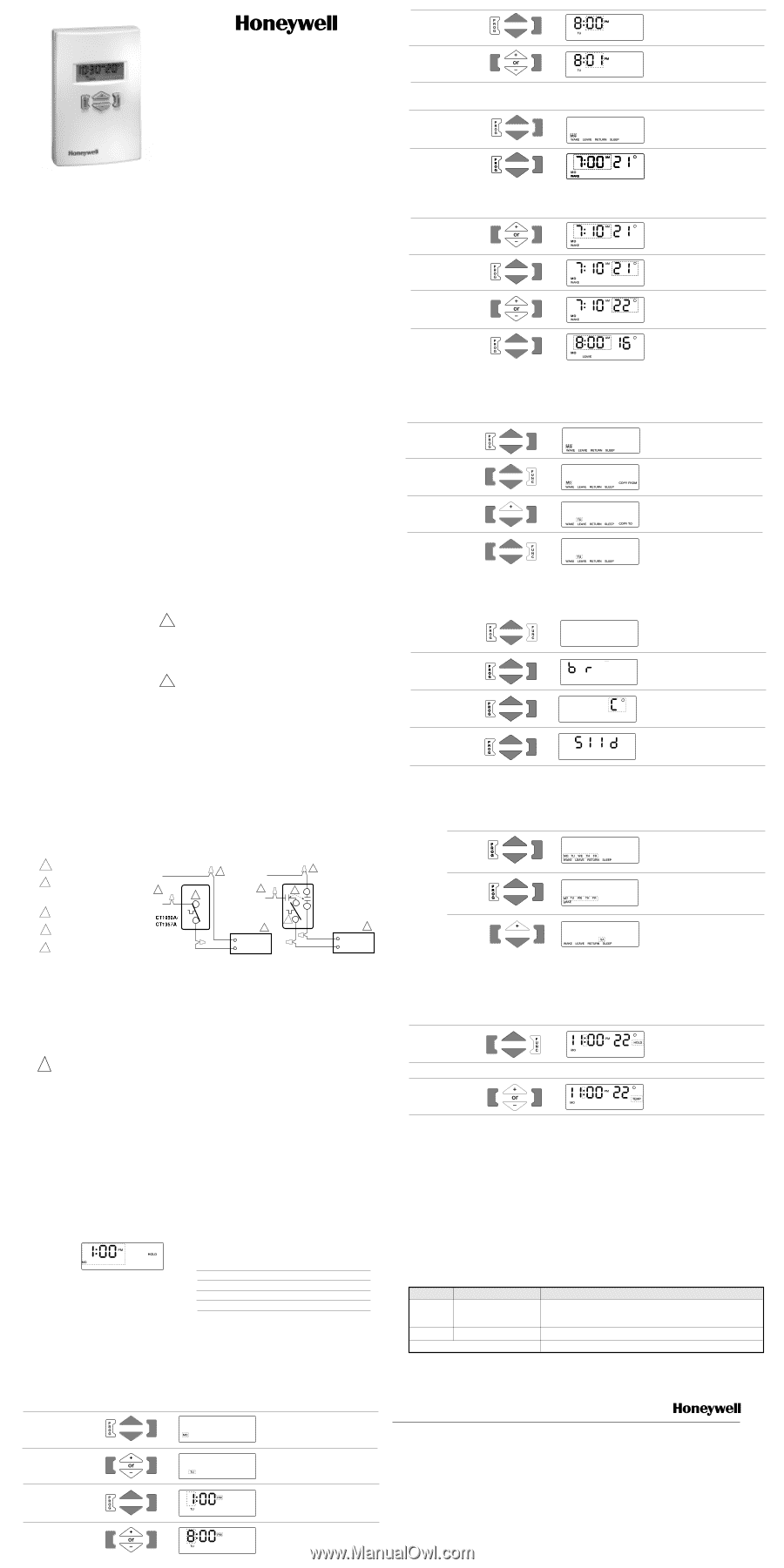
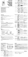
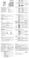
CT1950/CT1957 Chronotherm ™ Electronic Programmable Line Voltage Thermostat Your CT1950/CT1957 Programmable Electronic Line Voltage Thermostat features digital temperature sensing and control for energy efficient precision operation. It will provide the flexibility of 5-1-1 day or 7 day programming and exceptional comfort control of resistance-rated heating equipment.The patented CoolSwitch™ design offers long service life. Depending on local climate, night and day setback of space temperature can save up to 28% of the energy used to heat a controlled zone. According to the Electric Power Research Institute, precision temperature control also offers up to 12% energy saving during comfort periods compared with conventional bi-metallic electric heating thermostats. Contents Specifications 2 Installation 3 Wiring 4 Thermostat Programming 6 Initial Power-Up 6 Clock 7 Schedule: 7 days 8 5-1-1 days 12 Reset 6 Additional Functions 11 Change Display 11 Temporary Program Override 13 Indefinite Program Override 13 Copy Program From One Day to Another . . 10 Checkout 14 5 Display MINUTE of the Day 6 Change MINUTE of the Day THERMOSTAT PROGRAMMING - TEMPERATURE SETUP 7 Day Mode (factory default setting) Step Press This Key Display will look like this Description Scroll through to display showing the first 7 day of programming [beginning with MOnday] 8 Display WAKE time Note; Broken line outline indicates flashing characters 8 Step Press This Key Display will look like this Description 9 Change WAKE time in 10 minute increments 10 Display WAKE setpoint temperature 11 Change WAKE setpoint temperature Display LEAVE time. 12 Repeat the adjustments suggested in steps 9 - 11 for the LEAVE, RETURN and SLEEP periods 9 SPECIFICATIONS MODELS: CT1950A/CT1957A - SPST; Makes heating circuit on temperature fall. CT1950B - DPST; Makes heating circuit on temperature fall. Breaks both sides of 240 volt line with switch in "OFF" position. Operating range: -20 to +104°F [-30 to +40°C], 5 to 95% RH, non-condensing. CONTROL RANGE: 7 to 27°C [45 to 80°F] in 1° increments. Factory set at 16°C [61°F] . SWITCHING: Patented CoolSwitch™ thyristor with relay conductor. WIRING CONNECTIONS: 6" [150 mm] stranded copper leadwires suitable for connection to aluminum wiring if approved special service CO/ALR connectors are used. ELECTRICAL RATINGS, NON-INDUCTIVE: 16 A (3800W) maximum, 2 A (500W) minimum @ 240V, 60 Hz. (12 ft. of baseboard maximum) SENSING ELEMENT: Electronic thermistor. 2 COPY FROM - AND COPY TO - ANOTHER DAY Step Press This Key Display will look like this 13 Description Select and display the day to be copied, e.g. MOnday Press key to display COPY FROM 14 15 16 Note: To exit the programming mode at any time, press 10 and hold the PROG key for 3 seconds. Select and display TUesday program period (pressing key will display COPY TO) Finally, press FUNC to enter this program. Repeat process for each day copied Broken line outline indicates flashing characters INSTALLATION ! WARNING • This thermostat is a line voltage (240 Vac) control. Do not install it unless you are completely familiar and competent with house wiring. If improperly handled, there can be a risk of 240 Volt electric shock hazard which may cause serious injury or death. • The CT1950/CT1957 is rated for normal full load current on a dual residential 20 A circuit breaker or fuse block. Do not use on circuits protected by higher-rated over-current protection devices. Some sustained fault conditions can cause product failure. • Do NOT connect to voltage different from device rating. ! CAUTION • Disconnect power supply before making wiring connections to prevent electrical shock or equipment damage. • All wiring must comply with applicable codes and ordinances. • Thermostats are designed to be used with appliances having a limit control. • Maximum load for thermostat must not exceed 3800W, otherwise a potential fire hazard exists. (ie. greater than 12 ft. of baseboard) LOCATION: Install a vertical switch box for mounting the CT1950/CT1957 approximately 1.5 m (5 ft.) above the floor on an inside wall where the thermostat will be subjected to average room temperature. The thermostat must be placed away from concealed warm or cold water pipes, air ducts, or drafts from hallways, fireplaces or stairways to sense temperature properly. Do not place thermostat above heater. 3 THERMOSTAT PROGRAMMING - ADDITIONAL FUNCTIONS To change display 17 FF FF Press and hold both the PROG and FUNC keys. Initially a random 4 digit/letter display will occur. 18 Convert to °C or °F 19 Convert 5-1-1 to 7-day 20 36 11 Press PROG key and continue - ("b" will appear for b model only). Press PROG key a second time to display C°. Use [+] key to change to F° if desired (or F° to C°) Press PROG key a third time to display "5 1 1 d"; press [+] key to change mode to 7-day programming (or vice versa) WIRING: 1. Disconnect power while installing. Double check that thermostat is rated for voltage and amperage of load to be controlled. 2. Remove cover as needed by carefully prying at the top or bottom edge with a coin or slot screwdriver. Fig. 1 Wiring 1 Power supply. Provide disconnect means (A) and overload protection as required. L2 2 Special service CO/ALR solderless (B) 2 L2 2 BLACK connections must be used when connecting aluminum conductors; otherwise, a fire hazard may result. 3 Thermostat breaks heating circuit on 1 3 L1 L1 BLACK 1 L1 BLACK CT1950B 5 L2 L1 T2 temperature rise. CCTT1199505A0A/ / T1 CT1957A 4 Thermostat is designed to be used with 3 T1 4 RED RED appliances equipped with a limit control. BLACK ELECTRIC 5 B Model thermostat breaks both sides of HEATER line with switch in OFF position 4 4 ELECTRIC HEATER THERMOSTAT PROGRAMMING ADDITIONAL FUNCTIONS cont'd THERMOSTAT PROGRAMMING: 5-1-1 Day Mode (refer to steps 17-20) Step Press This Key Display will look like this 21 22 Description Scroll through the displays until the screen shows the MOnday to FRiday schedule with the WAKE, LEAVE RETURN and SLEEP options Follow the same programming proceedure as steps 8-12 23 Note: Broken line outline indicates flashing characters 12 Program SAturday and SUnday separately or use the "Copy From - Copy To" feature (steps 13-16) cont'd WIRING cont'd 3. When replacing an old line voltage wall thermostat, remove it carefully to avoid damage to the insulation on the wiring. Check the old insulation for cracks, nicks, or fraying and apply certified electrical tape where necessary to achieve adequate insulation, or replace the wires in an approved fashion. 4. Attach wires with solderless wire connectors approved for the size and number of wires to be connected. Be sure that all wire connectors are tight. CAUTION: Do not short 240 V supply wires with thermostat connected. This will damage the CT1950/CT1957 and void the warranty. ! WARNING: To avoid risk of fire hazard, all connections to aluminum conductors must be made using approved CO/ALR solderless connectors. 5. Secure thermostat to the electrical box with captive mounting screws. Installation Hint: Prebend the solid conductors, then push them and the wire connectors into the electrical box before tightening the mounting screws. 6. Snap cover in place. 7. Turn power on. TO INDEFINITELY OVERRIDE A PROGRAM Step Press This Key 24 TO TEMPORARILY OVERRIDE A PROGRAM 25 Display will look like this Description Press and release FUNC key to activate the HOLD mode. Press and hold PROG key to return to RUN mode. Press and hold [+] or [-] key until TEMP appears on screen; adjust temperature [+] or [-] as desired. Thermostat will return to normal program status automatically in next period 5 THERMOSTAT PROGRAMMING INITIAL POWER-UP On first power up, the thermostat display will show a self test 00 E status, display for about 15 seconds, then go blank for one second, followed by this display - (broken line indicates section is flashing.) The thermostat will begin temperature control with the default setpoint at 61°F (16°C) in the HOLD mode. It will continue to operate in this manner until the user presses PROG and proceeds to set the clock (Step 1) below. days (see Table 1 below). After the clock is set up, if the factory set schedule is satisfactory, no more programming is required. The thermostat will revert to normal RUN mode either by pressing and holding the PROG key for 3 seconds, or left untouched for 5 minutes. Table 1 - Initial Factory Schedule for 7-day Event Time Temperature WAKE 6:00 a.m. 21°C (70°F) LEAVE 8:00 a.m. 16°C (61°F) RETURN 6:00 p.m. 21°C (70°F) SLEEP 10:00 p.m. 16°C (61°F) Note: To Change display or functions (e.g. to °C or °F, or programming from 5-1-1 to 7-day) see instructions on Additional Functions, p. 11. FACTORY SET PROGRAMMING The thermostat is preset with a factory set schedule for 7 THERMOSTAT RESET The reset key is accessed by inserting a bent paperclip or similar wire into the small hole next to the [+] key (with cover removed). This will reset the clock only, programmed schedule will be retained. 6 THERMOSTAT PROGRAMMING CLOCK SETUP Step Press This Key Display will look like this Description 1 Display DAY of the Week 2 Change DAY of the Week 3 Display HOUR of the Day 4 Change HOUR of the Day 7 13 CHECKOUT When the thermostat is first powered up (or after 8 hours of continuous power loss), the display will blink for 2 seconds, OOE then undergo a self test, indicated by for 15 seconds. Once the display shows 1:00 pm flashing, the internal checkout is complete, and the thermostat is ready to program. To verify the thermostat is turning on the baseboard heater, repeatedly press the [+] key until the displayed setpoint exceeds the room temperature. The [°] symbol should be flashing. Feel near the baseboard heating element and the unit should be starting to generate heat. Press and hold the PROG key and the thermostat will return to its former RUN mode. TROUBLE SHOOTING Display Code Cause Action OLOAd Connected load exceeded Ensure that total wattage of baseboard connected do not exceed 3800W. 3800W A fire hazard exists if wattage exceeds 3800W. Push reset key to clear and reset clock. 06E Power failure detected Push reset key to clear and reset clock. Missing segment or other abnormal display Push reset key to clear and reset clock. If problem persist call Honeywell. 14 Automation and Control Solutions Honeywell Honeywell Limited-Honeywell Limité e 1985 Douglas Drive North 35 Dynamic Drive Golden Valley, MN 55422 Scarborough, Ontario MIV 4Z9 G.H. • 6/02 • © Honeywell Limited 69-1644EF
-
 1
1 -
 2
2
 |
 |