69-1642
OWNER°S GUIDE
fi U.S. Registered Trademark
Copyright ' 2002 Honeywell °
°All Rights Reserved
Honeywell CT3600/CT3697
PROGRAMMABLE THERMOSTAT
Seven Day Programmable Heat and/or Cool
Low Voltage (20 to 30 Vac) Thermostat and Wallplate
Model CT3600/CT3697
Para obtener un documento con las instrucciones en espaæol, por favor visite
nuestro sitio de web a: www.honeywell.com/yourhome.
Pour obtenir des notices techniques en fran±ais, veuillez consulter notre site web
www.honeywell.com/yourhome.
Contents
Step 1. Prepare for Installation
...................................................................................................................................
5
Step 2. Remove Old Thermostat
................................................................................................................................
6
Step 3. Mount Thermostat Wallplate
..........................................................................................................................
7
Step 4. Wire Wallplate Terminals
................................................................................................................................
8
Step 5. Install the Batteries
.........................................................................................................................................
9
Step 6. Set Fan Operation Switch
..............................................................................................................................
10
Step 7. Mount the Thermostat
....................................................................................................................................
11
Step 8. Customize Your Thermostat
...........................................................................................................................
11
Step 9. Set the Clock
..................................................................................................................................................
13
Step 10. Programming
................................................................................................................................................
14
Step 11. Operating Your Thermostat
..........................................................................................................................
17
Step 12. Set the Fan and System Switches
...............................................................................................................
19
If You Have a Problem
................................................................................................................................................
20
Smart Response™ Technology
..................................................................................................................................
21
Wiring Diagrams
.........................................................................................................................................................
22

 1
1 2
2 3
3 4
4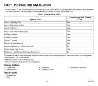 5
5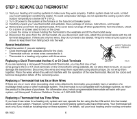 6
6 7
7