Honeywell H46E1013 Installation Instructions - Page 2
Setting And Adjustment, Checkout - dehumidistat
 |
UPC - 085267047463
View all Honeywell H46E1013 manuals
Add to My Manuals
Save this manual to your list of manuals |
Page 2 highlights
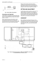
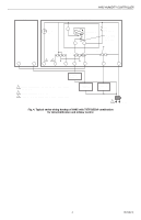
H46C HUMIDITY CONTROLLER POWER SUPPLY 1 H46C HUMIDITY CONTROLLER RISE L1 (HOT) L2 DEHUMIDIFIER EXHAUST FAN OR AIR CONDITIONER 1 PROVIDE DISCONNECT MEANS AND OVERLOAD PROTECTION AS REQUIRED. M7923 Fig. 2. Typical H46C wiring diagram. Connections and Operation A dehumidistat in combination with the thermostat can be used to run the air conditioner to control relative humidity levels. The dehumidistat and thermostat can be wired in parallel or in series. Wiring in parallel allows the dehumidistat to indepen dently control the humidity level, but could cause overcooling of the home. During unoccupied times, the homeowner should set the thermostat to a relatively high setting and control moisture using the dehumidistat. Wiring in series prevents overcooling but the air conditioner runs only when both the thermostat and dehumidistat are calling. During unoccupied times, the homeowner should set the thermostat to a relatively low setting and control moisture using the dehumidistat. SETTING AND ADJUSTMENT The H46 makes contact on a relative humidity rise to the setpoint to start the dehumidifier. On a decrease in relative humidity to the setpoint (minus the differential), the switch breaks contact to stop the dehumidifier. Turn the knob clockwise to the setting stop to place the H46 in the On position. Turn the knob counterclockwise to the setting stop to place the H46 in the Off position. CHECKOUT After completing all mounting and wiring, turn on the power supply. Place the system into operation by turning the setting knob toward the low end of the scale until the dehumidifier motor starts. Turn the setting knob slowly toward the high end of the scale until the dehumidifier motor stops. H46C R H FILTER LIGHT T87F/Q539A INTERNALSCHEMATIC T87F R1 TEMPERATURE FALL W1 Y1 FIXED COOL ANTICIPATOR ADJUSTABLE HEAT ANTICIPATOR HEAT OFF COOL HEAT OFF COOL AUTO FAN ON 3 2 X B O W Y G R HEATING RELAY OR VALVE COIL 1 PROVIDE OVERLOAD PROTECTION AND DISCONNECT MEANS AS REQUIRED. 2 HEATING DAMPER MOTOR, IF USED. 3 CLOGGED FILTER SWITCH OR COOLING PANEL CONNECTION. COOLING CONTACTOR COIL FAN RELAY COIL 1 Fig. 3. Typical parallel wiring hookup for H46C with T87F/Q539A combination for dehumidification and mildew control. M7913 95-5367-4 2
-
 1
1 -
 2
2 -
 3
3 -
 4
4
 |
 |