Honeywell HE360A1027 Installation Guide - Page 5
Installing the Humidistat - humidifier
 |
View all Honeywell HE360A1027 manuals
Add to My Manuals
Save this manual to your list of manuals |
Page 5 highlights
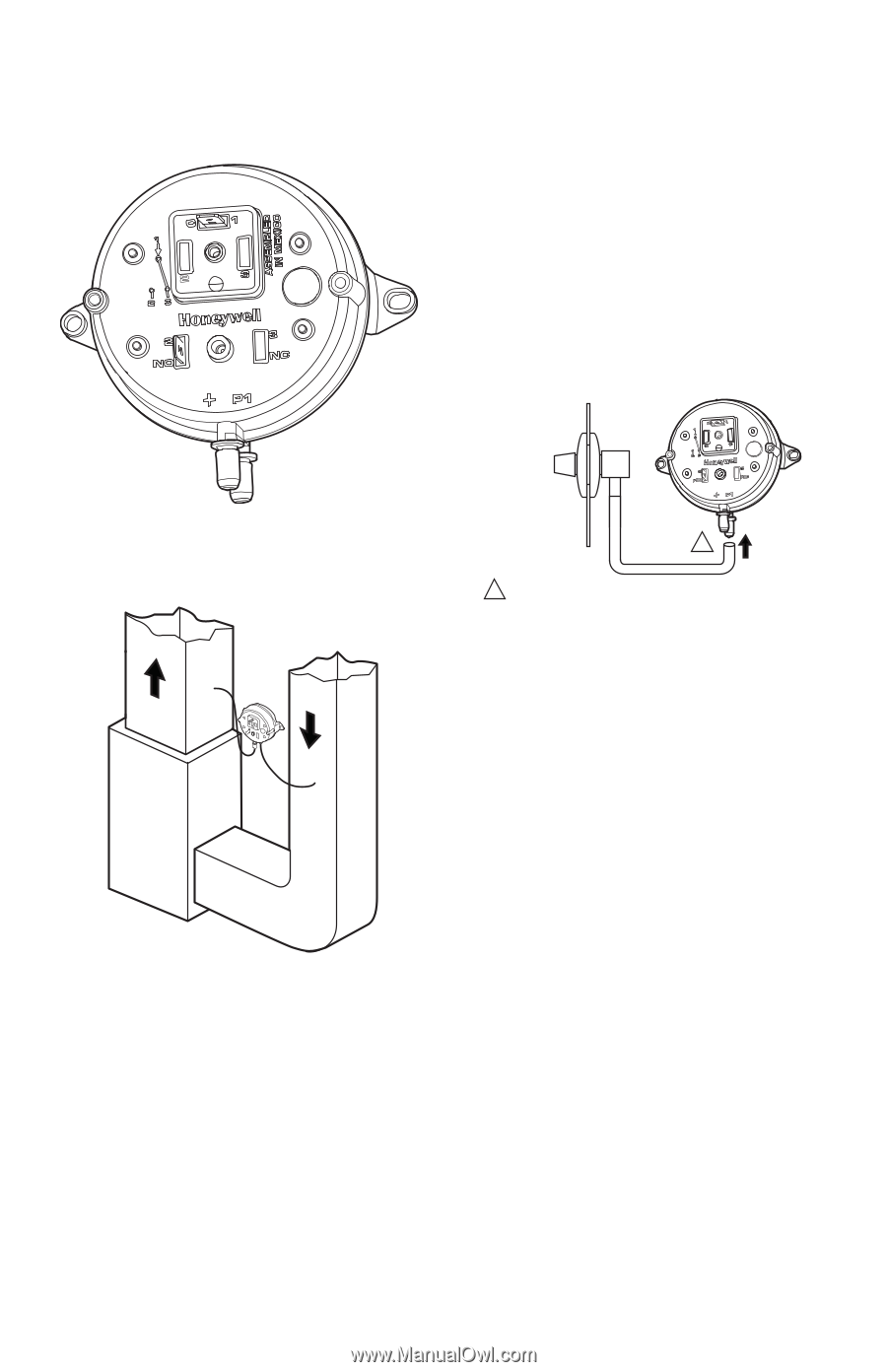
HE360 HUMIDIFIER AND INSTALLATION KIT IMPORTANT Calibration accuracy requires that the switch be mounted vertically (as pictured in Fig. 8). 4. Cut a 3/4-in. diameter hole in the duct within 10 feet of the switch to ensure the provided tubing reaches the pressure tap elbow. 5. Insert the black rubber gasket into the duct hole. 6. Connect the tubing to the tubing fitting elbow and insert the tubing fitting elbow into the black rubber gasket. 7. Connect the other end of the tubing to the applicable pressure connection on the switch. e. Black connection if installed on the supply f. Grey connection if installed on the return g. Both grey and black if installed on both IMPORTANT With low-speed airflow or variable speed systems it is recommended to run tubing to both the supply and return ducts. M27300 Fig. 8. Pressure switch-oriented vertically. 3. The return duct is recommended, however the switch can also be mounted to the supply duct. A B SUPPLY DUCT INSTALL - AIR LINE ONLY TO TAP A, CONNECTED TO THE + PORT ON THE AIR FLOW SWITCH RETURN DUCT INSTALL - AIR LINE ONLY TO TAP B, CONNECTED TO THE - PORT ON THE AIR FLOW SWITCH SUPPLY/RETURN DUCT INSTALL - AIR LINE CONNECTED TO BOTH THE + AND - PORTS ON THE AIR FLOW SWITCH M27303 Fig. 9. Mounting the pressure switch. INSIDE OF DUCT 1 1 CONNECT TUBING TO + CONNECTION IF PRESSURE TAP IS MOUNTED TO SUPPLY DUCT. CONNECT TO - IF PRESSURE TAP IS MOUNTED TO RETURN DUCT. M27304 Fig. 10. Install tubing. 8. You may cut the tubing to fit the connection length between the tubing fitting elbow and switch. It is also recommended to secure the hose to existing structures to avoid accidental disconnection. Installing the Humidistat Installing on Mounting Duct 1. Apply the template to the duct location chosen for the humidistat. Make sure the template is level before drilling the holes. 2. Refer to the template (provided with the H8908 Humidistat Installation Instructions) to drill the control assembly opening and mounting holes for the H8908. 3. Remove the H8908 case from the base. 4. Position the foam gasket on the H8908 base. 5. Position the base on the duct with the arrow up. 6. Secure the base to the duct using the four 1 in. (25 mm) mounting screws provided with humidistat. 7. Connect the low-voltage wires to the leads and replace the H8908 case. See Fig. 12. NOTE: For wall mounting instructions, see the H8908 Installation Instructions. 5 69-2517EF-01
-
 1
1 -
 2
2 -
 3
3 -
 4
4 -
 5
5 -
 6
6 -
 7
7 -
 8
8 -
 9
9 -
 10
10 -
 11
11 -
12
-
13
-
14
-
15
-
16
-
17
-
18
-
19
-
20
 |
 |