Honeywell MS9540-38-3 User Guide - Page 8
Scanner Components, Visual Indicators, How to use CodeGate, Audible Indicators, The PowerLink Cable
 |
View all Honeywell MS9540-38-3 manuals
Add to My Manuals
Save this manual to your list of manuals |
Page 8 highlights
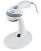
INTRODUCTION Scanner Components No. Item Description 1 Green LED* See Visual Indicators on page 18 2 Red LED* See Visual Indicators on page 18 3 Yellow LED** See Visual Indicators on page 18 4 Button** See How to use CodeGate on page 12 5 Red Window LED Aperture 6 Speaker See Audible Indicators on page 17 7 Cable Release Pin-Hole See The PowerLink Cable on page 5 8 Cable Connection 10-pin RJ45, Female Socket, See Scanner Pinout Connections on page 38 Figure 1. Scanner Components * In some custom units the standard green LED has been replaced with a blue LED and the red LED has been replaced with a white LED. ** Items are only provided with MS9540, VoyagerCG models. 4
-
 1
1 -
2
-
 3
3 -
 4
4 -
 5
5 -
 6
6 -
 7
7 -
 8
8 -
 9
9 -
 10
10 -
 11
11 -
 12
12 -
 13
13 -
14
-
15
-
16
-
17
-
18
-
19
-
20
-
21
-
22
-
23
-
24
-
25
-
26
-
27
-
28
-
29
-
30
-
31
-
32
-
33
-
34
-
35
-
36
-
37
-
38
-
39
-
40
-
41
-
42
-
43
-
44
-
45
-
46
-
47
-
48
-
49
-
50
-
51
-
52
-
53
-
54
-
55
-
56
 |
 |

4
I
NTRODUCTION
Scanner Components
No.
Item Description
1
Green LED*
See
Visual Indicators
on page 18
2
Red LED*
See
Visual Indicators
on page 18
3
Yellow LED**
See
Visual Indicators
on page 18
4
Button**
See
How to use CodeGate
on page 12
5
Red Window
LED Aperture
6
Speaker
See
Audible Indicators
on page 17
7
Cable Release Pin-Hole
See
The PowerLink Cable
on page 5
8
Cable Connection
10-pin RJ45, Female Socket,
See
Scanner Pinout Connections
on page 38
Figure 1. Scanner Components
*
In some custom units the standard green LED has been replaced with a
blue LED and the red LED has been replaced with a white LED.
** Items are only provided with MS9540, VoyagerCG models.