Honeywell YCT51N Owner's Manual - Page 3
Wiring CT50/CT53/CT54, Wiring CT51/CT55
 |
UPC - 085267271196
View all Honeywell YCT51N manuals
Add to My Manuals
Save this manual to your list of manuals |
Page 3 highlights
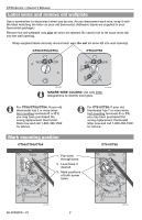
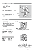
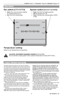
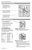
English: Page 1 • Français : Page 6 • Español: Página 11 Mount thermostat base 1. Drill holes at pencil-marked locations (3/16" holes for drywall, 7/32" holes for plaster). 2. Use hammer to tap anchors into holes until flush with wall. 3. Pull wires through thermostat base and insert screws. Check level if desired, then tighten screws. M23791 Connect wires 1. Match each labeled wire with same letter on terminal. 2. Use a screwdriver to loosen screw terminals, insert bare wires beneath screws, then tighten screws. 3. Push any excess wire back into the wall opening. Labels don't match? If labels do not match letters on thermostat, see table below. Existing wires Connect to: R • RH • 4 • V Terminal "R" [1] Rc Terminal "Rc" [1] O Terminal "O" [2] B Terminal "B" [2] G • F Terminal "G" W • W1 • H Terminal "W" Y • Y1 • M Terminal "Y" C • X • B Do not use [3] CT50/CT53/CT54 Wiring CT50/CT53/CT54 • 2-wire heat-only system: Connect one wire to R terminal, one wire to W terminal. CT51/CT55 Wiring CT51/CT55 M23792 [1] If wires will be connected to both R and Rc terminals, remove the metal jumper. [2] Do not connect both O and B if you have a heat pump. Connect only the O wire. Wrap B wire with electrical tape and do not use. [3] Do not use C, X or B. Wrap bare end of wire with electrical tape. 3 69-2040EFS-01
-
 1
1 -
 2
2 -
 3
3 -
 4
4 -
 5
5 -
 6
6 -
 7
7 -
 8
8 -
 9
9 -
10
-
11
-
12
-
13
-
14
-
15
-
16
 |
 |
