Hotpoint RA724KWH Installation Instructions - Page 18
Wire Conduit Installation, Wire Conduit Installation, Replace The Wire Cover - voltage
 |
UPC - 084691131687
View all Hotpoint RA724KWH manuals
Add to My Manuals
Save this manual to your list of manuals |
Page 18 highlights
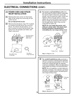
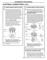
Installation Instructions ELECTRICAL CONNECTIONS (CONT.) 6 3-WIRE CONDUIT INSTALLATION A Loosen the 3 lower terminal screws from the terminal block. Insert the center bare wire (white/neutral) tip through the bottom center terminal block opening. On certain models, the wire will need to be inserted through the ground strap opening and then into the bottom center block opening. Insert the two side bare wire tips into the lower left and the lower right terminal block openings. Tighten the screws until the wire is firmly secure (approximately 20 inch-lbs.). NOTE: ALUMINUM WIRING: Aluminum building wire may be used but it must be rated for the correct amperage and voltage to make connection. Connect wires according to this Step 6 or Step 7 depending on number of wires. Terminal block Wire tips Bracket Conduit Wire used, location and enclosure of splices, etc., must conform to good wiring practices and local codes. B Skip to Step 8 and proceed with the installation. 7 4-WIRE CONDUIT INSTALLATION A Loosen the three lower terminal screws from the terminal block. Remove the ground screw and ground plate and retain them. Cut and discard the ground strap. DO NOT DISCARD ANY SCREWS. B Insert the ground bare wire tip between the range frame and the ground plate (removed earlier) and secure it in place with the ground screw (removed earlier). Insert the bare wire (white/neutral) tip through the bottom center of the terminal block opening. Insert the two side bare wire tips into the lower left and the lower right terminal block openings. Tighten the screws until the wire is firmly secure (approximately 20 inch-lbs.). Before Ground strap Terminal block Cut and discard the ground strap After Neutral terminal Terminal block Wire tips or Ground plate (grounding to range) Ground screw Bracket Wire used, location and enclosure of splices, etc., must conform to good wiring practices and local codes. C Proceed to Step 8. 8 REPLACE THE WIRE COVER Replace the wire cover on the range back by sliding its two lower retaining tabs into the slots and replacing the screw removed earlier. Make sure that no wires are pinched between the cover and the range back. 18
-
 1
1 -
2
-
3
-
4
-
5
-
6
-
7
-
8
-
9
-
10
-
11
-
12
-
 13
13 -
 14
14 -
 15
15 -
 16
16 -
 17
17 -
 18
18 -
 19
19 -
 20
20 -
 21
21 -
 22
22 -
 23
23 -
24
 |
 |
