Hunter 24852 Owner's Manual - Page 2
Installation, Ceiling, Plate, Plane, Decal
 |
View all Hunter 24852 manuals
Add to My Manuals
Save this manual to your list of manuals |
Page 2 highlights
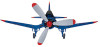
Step 4: Installation Of The Ceiling Plate CAUTION: Cover plate must be securely mounted, as it supports the entire weight of the fan. A. Drill two pilot holes, 9/64" diameter in the 2 x 4 brace at the outermost holes in the outlet box. Install the (3) rubber bushings into the top of the ceiling plate. Thread the wire leads through the center hole in the ceiling plate and attach the ceiling plate to the brace. Use (2) #10 x 3" woodscrews and washers for mounting. See Figure 4. Do not tighten screws at this time. Leave a ih" gap between the ceiling plate and the ceiling for insertion of the airplane decal. 1912/ " WING DECAL (2) WING JOINT LINE 2 x 4 WOOD BRACE OUTLET BOX CANOPY/TAIL DECAL MARK CEILING IN THESE LOCATIONS FOR EACH WING (HIDE MARKS UNDER WING) r MARK CEILING IN THESE LOCATIONS FOR EACH WHEEL (HIDE MARKS UNDER WHEEL) LANDING GEAR DECAL FIGURE 5 1„,'„ CEILING PLATE MOUNTING SCREWS FIGURE 4 BUSHINGS Step 5: Installation of Plane Decal Please follow the instructions carefully, to insure proper mounting of the decal. Read through first to understand the concept. WING DECAL (2) CANOPY/TAIL DECAL 11( 12 -1 F- 71" MARK CEILING IN THESE LOCATIONS FOR EACH WING (HIDE MARKS UNDER WING) DISK STRIP WING JOINT LINE LANDING GEAR DECAL FIGURE 5 CEILING PLATE C=D TAPE WITH CORNERS MARKED INSIGNIA FIGURE 6 elm • CD TAPE WITH CORNERS MARKED INSIGNIA CEILING PLATE FIGURE 6 The decal comes complete with pressure sensi tive tape and special clips to hold it to the ceiling. The decal is in four parts: the Landing Gear, Canopy/Tail and two Wings. Be sure the insignia emblem is mounted on top for the right wing and on bottom for the left wing. See Figure 6. The ceiling should be clean and dry for proper adhesion of the tape strips. A. Slide the Landing Gear decal and the Canopy/Tail decal behind the ceiling plate. Align the decals with the ceiling plate and with one wall for squareness. Tighten the screws on the ceiling plate just enough to hold the decals in place. Put two small pieces of tape under the corners of the Landing Gear decal as shown in Figure 6. Mark the tape to indicate the corners of the decal. This is extremely important as it will give you the exact location for the decal. Mark the positions of the wheels and the two wing joint lines as shown in Figure 5. Loosen the ceiling plate screws and remove the decals. B. Use a wood block to drive the clips into the ceiling as shown in Figure 7. Locate one clip between the two lines marked for each wheel and center one clip over each line marked where the wings join the Landing Gear decal. FORM NO. 41078-01 2/95 - 2 - ©1995 HUNTER FAN CO'
-
 1
1 -
 2
2 -
 3
3 -
 4
4
 |
 |
