Hunter 28686 Owner's Manual - Page 13
° Align the notches in the sides of the lower switch housing - fan model
 |
View all Hunter 28686 manuals
Add to My Manuals
Save this manual to your list of manuals |
Page 13 highlights
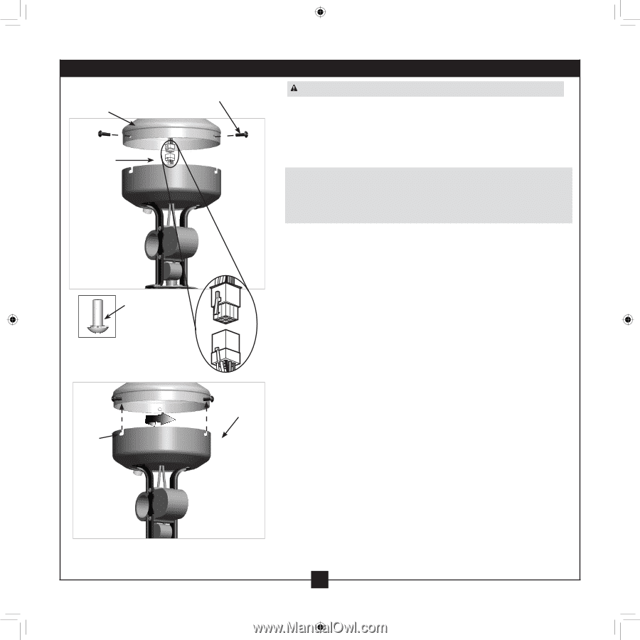
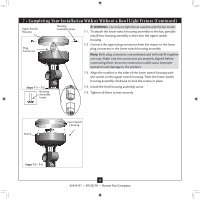
7 • Completing Your Installation With or Without a Bowl Light Fixture (Continued) Upper Switch Housing Plug Connector Housing Assembly Screw WARNING: Use only the light fixture supplied with this fan model. 7-1. To attach the lower switch housing assembly to the fan, partially install two housing assembly screws into the upper switch housing. 7-2. Connect the upper plug connector from the motor to the lower plug connector in the lower switch housing assembly. Note: Both plug connectors are polarized and will only fit together one way. Make sure the connectors are properly aligned before connecting them. Incorrect connection could cause improper operation and damage to the product. 7-3. Align the notches in the sides of the lower switch housing with the screws on the upper switch housing. Twist the lower switch housing assembly clockwise to lock the screws in place. Steps 7-1 - 7-2 Housing Assembly Screw 7-4. Install the third housing assembly screw. 7-5. Tighten all three screws securely. Notch Lower Switch Housing Steps 7-3 - 7-5 13 42443-01 • 09/20/10 • Hunter Fan Company
-
 1
1 -
2
-
3
-
4
-
5
-
6
-
7
-
 8
8 -
 9
9 -
 10
10 -
 11
11 -
 12
12 -
 13
13 -
 14
14 -
 15
15 -
 16
16 -
 17
17
 |
 |