Hunter 42999 Owner's Manual - Page 2
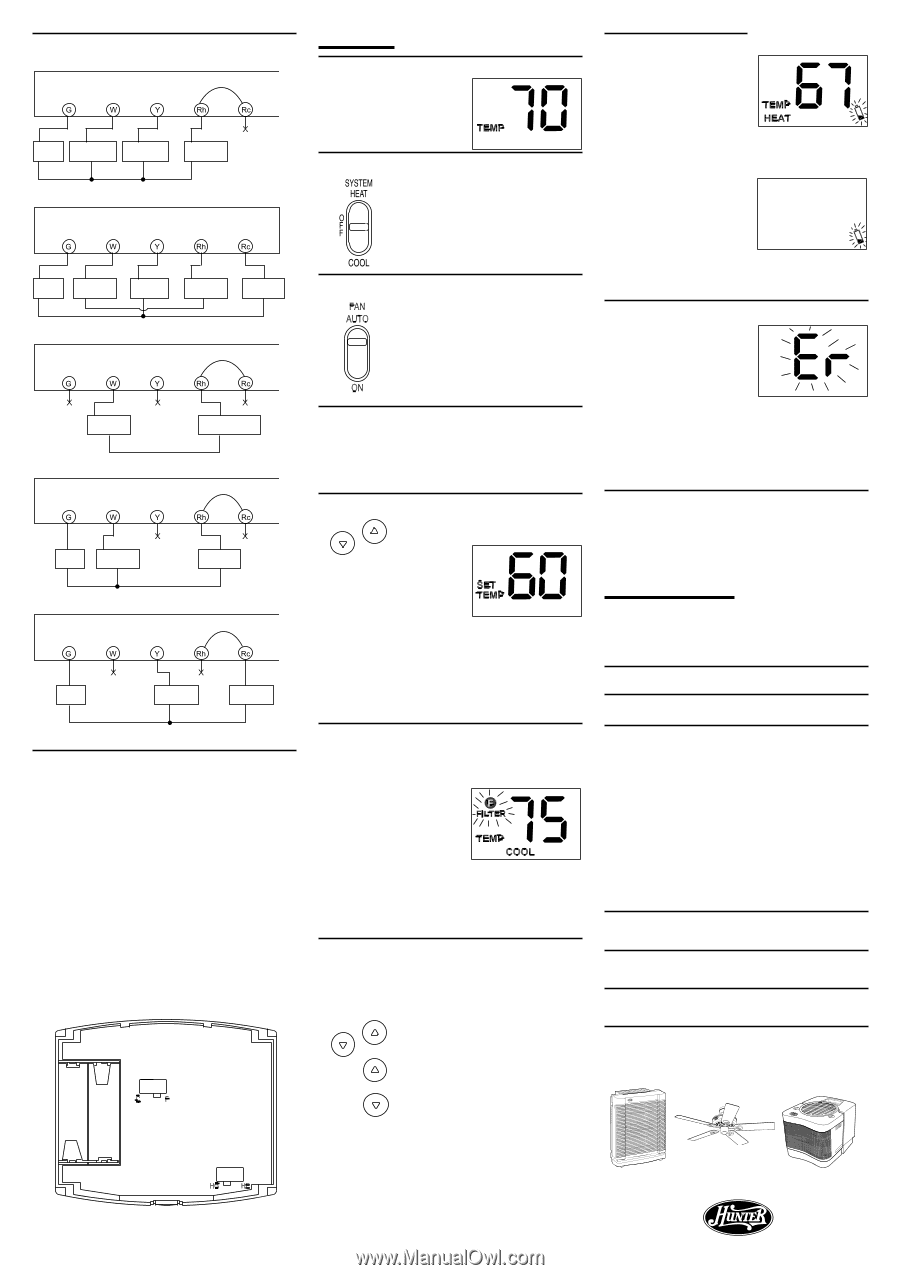
OPERATION, Solution, Problem, TROUBLESHOOTING - review
 |
View all Hunter 42999 manuals
Add to My Manuals
Save this manual to your list of manuals |
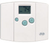
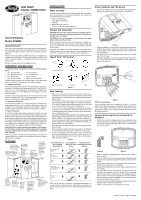
Page 2 highlights
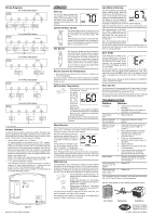
Wiring Diagrams 4-wire Heat/Cool System Wallplate Terminals Jumper Fan Relay Heat Relay or Valve Cool Contactor Heat/Cool 24V Supply Wallplate Terminals 5-wire Heat/Cool System No Jumper Fan Relay Heat Relay or Valve Cool contactor Heat 24V Supply Cool 24V Supply Wallplate Terminals 2-wire Heat Only System Jumper Heat Relay or Valve Heat 24V or Millivolt Supply Wallplate Terminals 3-wire Heat Only System Jumper Fan Relay Heat Relay or Valve Heat 24V Supply Wallplate Terminals 3-wire Cool Only System Jumper Fan Relay Cool contactor Cool 24V Supply X - No Connection Selector Switches In order for this thermostat to control your system, the system type must be specified by the selector switches on the printed circuit board inside the thermostat. There is also a selector switch for your choice of Fahrenheit or Celsius temperature display. • Heating System Selector (HG - HE switch) The factory position for this switch is in the "HG" position. Leave it in this position if you have a gas furnace or an oil burner. If you have an electric furnace, test to see whether the Heat and Fan come on as expected after installation. If the Fan operation is normal, leave it in the "HG" position. If the Fan does not come on within a minute of the thermostat calling for heat, change the switch position to "HE". The system selector has no effect in the cooling mode. NOTE: "HG" position is for gas and most other systems. "HE" position is for certain electric systems having a fan relay. • F° / C° selector (Fahrenheit / Celsius) Your thermostat is set for F° mode from the factory. In order to change to C° mode, slide the switch to C° and press the reset button on front of the thermostat with a paper clip. NOTE: Unless the reset button is pressed, the thermostat will not change temperature mode. Temperature Display (SW4) Fan Option (SW3) Figure 6 Form No. 41497-01 Rev 6-29-2001 OPERATION Start-up The LCD will show the factory default display of 70°F (21°C) when batteries are first installed, or after the Reset button is pressed. The temperature will update after a few seconds. System Selector Switch The System Selector switch on the front of the thermostat determines the operating mode of the thermostat. You may select COOL, OFF, HEAT. NOTE: Anytime you install or remove the thermostat from the wallplate, slide the System Selector to the OFF position to prevent the possibility of a rapid system On-Off. Fan Switch The Fan switch should normally be located in the AUTO position. The Fan will be turned on along with normal operation of your system. In a normal gas or oil furnace, the Fan will be turned on by your furnace after its warm-up delay. For electric heat and air conditioning operation, the Fan will turn on with the system. To run the Fan on continuously, slide the Fan switch to the ON position. Review Current Set Temperature • Press either the up or down key for less than 1 second to see the Set Temperature. The factory default is 68°F (20°C) when started with the System Switch Off or Heat, and 78° (26°C) when started with the System Switch on Cool. Setting New Temperature • Press either the up or down key and hold for longer than 1 second. • The display will flash to show that you are in Set Temperature mode, then you can release the key. • Press either up or down again to change to your desired Set Temperature. Hold the key down for over 2 seconds to fast-advance the Set Temperature. The display will return to the normal room temperature after the keys have been released for 3 seconds. Filter Monitor The thermostat counts the number of hours your system's filter has been in use. To maximize your system's performance and energy efficiency, change or clean your filter regularly. When the total system run time for heat and cool reaches 400 hours, the Filter Change Indicator will flash as a reminder to check your system's filter. After changing or cleaning the system filter, press and hold the Filter key for 3 seconds. The display will blink, and the counter will be reset to zero. Note: Pressing the Filter key at any time for less than 3 seconds will cause the Filter Change Indicator to appear on the LCD. This is only to confirm key operation, and the counter is not affected unless the key is held for greater than 3 seconds. SPAN Setting Your thermostat is set at the factory to cycle at 1°F (0.5°C) above and below the set temperature. (Span = 2) This setting has been designed to provide a comfortable room temperature under most all conditions. However, if you find your system cycling too fast or too slow, then the Span can be adjusted to modify the cycle time. • Press and hold BOTH for three seconds. The display will flash, and SPAN will be displayed on the LCD. • Press to raise the Span to 3. This setting INCREASES the cycle time by allowing your system to run LONGER. • Press to lower the Span to 1. This setting DECREASES the cycle time by causing your system to run SHORTER. The Span settings remain the same for both HEAT and COOL, and can be changed in any System Switch position. When batteries are installed in the thermostat, or the Reset key is pressed, the Span is reset back to setting 2. Low Battery Warning Your thermostat has a two-stage low battery warning system. When the batteries are first detected to be weak, the first stage low battery warning is indicated by battery symbol flashing on the LCD display. At your earliest convenience, you need to replace the batteries with 2 new AA alkaline batteries. When the batteries become too weak for normal operation, the thermostat enters the second stage low battery warning which shuts down the thermostat. In this condition, "BATT" flashes alone on the display, and the thermostat will turn your system Off. Your system will remain shut-off until the batteries are replaced. Note: The thermostat will still keep the current Set Temperature and Filter run time in memory until new batteries are installed. After confirming that new batteries have been inserted, the thermostat will return to normal operation. Error Mode If the thermostat is unable to control your system due to an unexpected battery problem, the thermostat will enter Error Mode. In this condition, the thermostat flashes "Er" on the LCD display, and shuts off your system. To correct this problem, replace the batteries with 2 new AA alkaline batteries, even if you have recently replaced them. Next, use a paper clip to press the RESET button next to the keypad. You will need to reprogram your thermostat and confirm normal operation. If Error Mode returns, please call Technical Support at 1-888-8301326 for further information. Auto Cut Off Your thermostat will automatically cutoff in Heat mode if the room temperature rises above 95°F (35°C). It will cutoff in Cool mode if the room temperature drops below 45°F (7°C). Note that if your system has malfunctioned and no longer responds to thermostat controls, the Auto Cut-Off will have no effect. TROUBLESHOOTING Problem Solution No Display. 1. Check battery connections and batteries. 2. Press RESET button with a small pin and hold in for two seconds. Entire Display Dims. 1. Replace Batteries. Auto Fan Does Not 1. Move HG/HE selector to correct Turn On Properly. position. Heating or Cooling 1. Check that the function switch is in Does Not Go On the correct position ("HEAT" or or Off. "COOL"). 2. There may be as much as 4-minute delay before the system turns On - wait and check. (Compressor protection delay.) 3. Check your circuit breakers and switches to ensure there is power to the system. 4. Replace batteries. 5. Make sure your furnace blower door is closed properly. 6. If your system only uses 4-wires, be sure the jumper wire is installed between the Rc and Rh terminals. Erratic Display. 1. Press the reset button once with a small pin and hold for two seconds. Then reprogram. If unit continues to 1. Replace unit. operate in the Off position. Thermostat perma- 1. Replace unit. nently reads "HI", "LO", or "Er". If you experience any other problems, call 1-888-830-1326 from 8 AM to 5 PM Central Time for technical assistance. Ask Your Local Retailer for Other Quality Products from Hunter. Air Purifiers Ceiling Fans Humidifiers Hunter Fan Company 2500 FRISCO AVENUE ® MEMPHIS, TN 38114 © 2001, Hunter Fan Company
-
 1
1 -
 2
2
 |
 |