Hunter 81030 Owner's Manual - Page 18
A15 bulbs Not Included.
 |
View all Hunter 81030 manuals
Add to My Manuals
Save this manual to your list of manuals |
Page 18 highlights
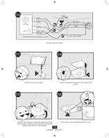
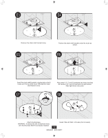
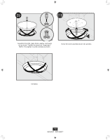
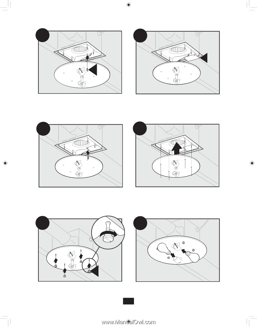
E3 E4 J K Remove the strain relief bracket screw. E5 Position the strain relief bracket under the motor as shown. E6 Insert the strain relief bracket's dog-leg tab so that it hooks over the lip of the motor. Reinstall the strain relief bracket screw. Align posts A, B, C and D (stamped into motor housing) with posts A, B, C and D (stamped into light fixture). Slide light fixture over posts. E7 E8 M Attach thumbscrews. WARNING: To reduce the risk of electrical shock, all 4 thumbscrews MUST be properly installed. 18 Install 2 Max 60 Watt A15 bulbs (Not Included). 43034-01 09/12/2011
-
 1
1 -
2
-
3
-
4
-
5
-
6
-
7
-
8
-
9
-
10
-
11
-
12
-
 13
13 -
 14
14 -
 15
15 -
 16
16 -
 17
17 -
 18
18 -
 19
19 -
 20
20 -
 21
21 -
 22
22 -
 23
23 -
24
-
25
-
26
-
27
-
28
-
29
-
30
-
31
-
32
-
33
-
34
-
35
-
36
-
37
-
38
-
39
-
40
-
41
-
42
 |
 |
43034-01
09/12/2011
18
E6
E8
E7
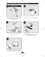
M
Attach thumbscrews.
WARNING: To reduce the risk of electrical shock,
all 4 thumbscrews MUST be properly installed.
Install 2 Max 60 Watt
A15 bulbs (Not Included).
J
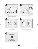
E5
Align posts A, B, C and D (stamped into motor housing)
with posts A, B, C and D (stamped into light fixture).
Slide light fixture over posts.
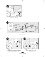
Remove the strain relief bracket screw.
Position the strain relief bracket under the motor as
shown.
Insert the strain relief bracket’s dog-leg tab so that it
hooks over the lip of the motor. Reinstall the strain
relief bracket screw.
K
E3
E4