Husqvarna 12527HV Owners Manual - Page 11
To Move Forward And Backward See Fig. 16 - spark plug location
 |
View all Husqvarna 12527HV manuals
Add to My Manuals
Save this manual to your list of manuals |
Page 11 highlights
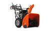
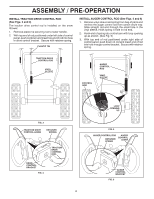
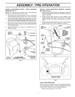
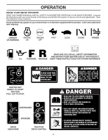
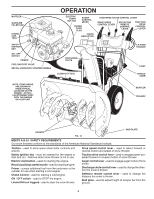
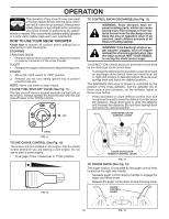
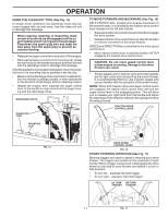
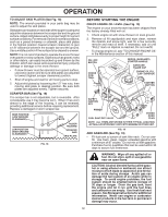
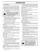
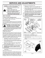
OPERATION USING THE CLEAN-OUT TOOL (See Fig. 15) In certain snow conditions, the discharge chute may become clogged with ice and snow. Use the clean-out tool to dislodge this blockage. When cleaning, repairing, or inspecting, make certain all controls are disengaged and the auger/impeller and all moving parts have stopped. Disconnect the spark plug wire and keep the wire away from the spark plug to prevent accidental starting. • Release the auger control lever and shut off the engine. • Remove the clean-out tool from it's mounting clip. Grasp the tool firmly by the handle and push and twist the tool into the discharge chute to dislodge the blockage. After the packed snow has been dislodged, return the cleanout tool to it's mounting clip by pushing it into the clip. • Make sure the discharge chute is pointed in a safe direction (no vehicles, buildings, people, or other objects are in the direction of discharge) before restarting engine. • Restart the engine, then squeeze the auger control lever to the handle to clear snow from the auger housing and the discharge chute. DISCHARGE CHUTE CLEAN-OUT TOOL TO MOVE FORWARD AND BACKWARD (See Fig. 16) SELF-PROPELLING, forward and reverse movement of the snow thrower, is controlled by the traction drive control lever located on the left side handle. • Squeeze traction drive control lever to handle to engage the drive system. • Release traction drive control lever to stop the forward or reverse movement of the snow thrower. SPEED and DIRECTION are controlled by the drive speed control lever. • Move speed control lever to desired position AFTER engaging the traction drive control lever. CAUTION: Do not move speed control lever unless engine is running. Damage to the snow thrower can result. • Slower speeds are for heavier snow and faster speeds are for light snow and transporting the snow thrower. It is recommended that you use a slower speed until you are familiar with the operation of the snow thrower. NOTE: When both traction drive and auger control levers are engaged, the traction drive control lever will lock the auger control lever in the engaged position. This will allow you to release your right hand from the handle and adjust the discharge chute direction without interrupting the snow throwing process. TRACTION DRIVE CONTROL LEVER MOUNTING CLIP FIG. 15 DRIVE SPEED CONTROL LEVER FIG. 16 POWER STEERING OPERATION (See Fig. 17) Steering triggers are used to assist in steering your snow thrower. The triggers are located on the underside of each handle. When a trigger is squeezed, it disengages the drive wheel on that side of snow thrower and allows it to turn in that direction. • To turn left - squeeze left side trigger. • To turn right - squeeze right side trigger. LH TURN RH TURN TRIGGER TRIGGER 11 FIG. 17
-
 1
1 -
2
-
3
-
4
-
5
-
 6
6 -
 7
7 -
 8
8 -
 9
9 -
 10
10 -
 11
11 -
 12
12 -
 13
13 -
 14
14 -
 15
15 -
 16
16 -
17
-
18
-
19
-
20
-
21
-
22
-
23
-
24
-
25
-
26
-
27
-
28
 |
 |