Husqvarna 325L Owners Manual - Page 12
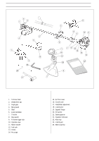
ASSEMBLY, Assembly of the trimmer head, Assembling the loop handlebar, 322L, 325L-X/L-XT, 325CX - parts diagram
 |
View all Husqvarna 325L manuals
Add to My Manuals
Save this manual to your list of manuals |
Page 12 highlights
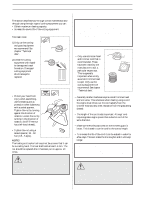
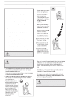
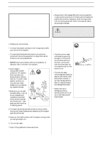
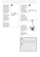
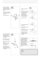
ASSEMBLY Assembling the loop handlebar (322C, 325CX) • Position the handle on the shaft. Note that the handle must be mounted below the arrow on the shaft. • Fit the bolt, securing plate and wing nut as shown in the diagram. • Tighten the wing nut. Assembling and dismantling the two-part shaft (325L-XT) Assembling: • Make sure the handle is loose. • Guide the cut-out on the lower section of the shaft into the coupling's locking plate on the upper section of the shaft. The sections are then locked together. • Tighten the handle. Assembling the loop handlebar (322L, 325L-X/L-XT) • Clip the loop handle onto the shaft. Note that the loop handle must be fitted between the arrows on the shaft. • Slide the spacer into the slot in the loop handle. • 322L: Fit the nut, washer and bolt. 325L-X/L-XT: Fit the nut, knob and bolt. Do not overtighten. • Now adjust the trimmer to give a comfortable working position. Tighten the bolt/knob. 12 - English Dismantling • Undo the handle (at least three turns). • Press the handle towards the coupling. • Carefully twist the lower section out of the lock. • Hold both parts of the shaft and pull out the lower section from the coupling. Assembly of the trimmer head It is extremely important that the disc drive's/support flange's guide engages correctly in the cutting equipment's centre hole when assembling the cutting equipment. Cutting equipment assembled incorrectly can result in serious and/or fatal personal injury. WARNING! Under no circumstances may the cutting ! equipment be used without an approved guard fitted. See the chapter "Technical data". If the wrong guard or a defective guard is fitted this can cause serious personal injury.
-
 1
1 -
2
-
3
-
4
-
5
-
6
-
 7
7 -
 8
8 -
 9
9 -
 10
10 -
 11
11 -
 12
12 -
 13
13 -
 14
14 -
 15
15 -
 16
16 -
 17
17 -
18
-
19
-
20
-
21
-
22
-
23
-
24
-
25
-
26
-
27
-
28
-
29
-
30
-
31
-
32
-
33
-
34
-
35
-
36
 |
 |
