Husqvarna GT52XLS Owners Manual - Page 21
ATTACH REAR LIFT LINKS C - Lift rear corner - replacement blades
 |
View all Husqvarna GT52XLS manuals
Add to My Manuals
Save this manual to your list of manuals |
Page 21 highlights
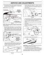
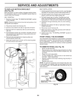
SERVICE AND ADJUSTMENTS • From right side of mower, first insert 90° end of anti-sway bar (S) into hole in transaxle bracket (T), located near left rear tire in front of transaxle. NOTE: Flashlight may be helpful. ANTI-SWAY BAR (S) LOCATION TRANSAXLE BRACKET (T) LOCATED BETWEEN REAR TIRES • ATTACH REAR LIFT LINKS (C) - Lift rear corner of mower and position slot in link assembly over pin on rear mower bracket (D) and secure with washer and retainer spring. • Repeat on opposite side of tractor. C PLACE 90° END INTO HOLE S T S. ANTI-SWAY BAR T. TRANSAXLE BRACKET Fig. 26 NOTE: Depending on model, bracket (T) may be different than shown but hole for anti-sway bar will be in same position/location. • Pivot the integrated washer end of anti-sway bar (S) towards mower deck bracket on right side of mower. Insert integrated washer end of bar into hole in rear mower bracket (D). Move mower as needed to insert integrated washer end of bar into rear mower bracket (D). • Secure with small washer and small retainer spring as shown. TS D D. RIGHT SIDE REAR MOWER BRACKET S. ANTI-SWAY BAR T. TRANSAXLE BRACKET Fig. 27 • ATTACH MOWER SIDE SUSPENSION ARMS (A) TO CHASSIS - Position hole in arm over pin (B) on outside of tractor chassis and secure with retainer spring. • Repeat on opposite side of tractor. A B D Fig. 29 • ATTACH FRONT LINK (E) - Work from left side of tractor. Insert threaded rod end of link assembly through front hole in tractor suspension bracket (F). • Install bushing (O) and loosely install nut (P) and jam nut (Q). • Insert flared ends of link (E) into slots in front mower bracket (H). • Check Front-To-Back Adjustment in "TO LEVEL MOWER" in this section. F O P E Q H Fig. 30 • Install belt onto electric clutch pulley (M). M Fig. 31 IMPORTANT: CHECK BELT FOR PROPER ROUTING IN ALL MOWER PULLEY GROOVES. • Raise attachment lift lever to highest position. • If necessary, adjust gauge wheels before operating mower as shown in the Operation section of this manual. See Mower Drive Belt Installation in "TO REPLACE MOWER BLADE DRIVE BELT" in this section of the manual. Fig. 28 21
-
 1
1 -
2
-
3
-
4
-
5
-
6
-
7
-
8
-
9
-
10
-
11
-
12
-
13
-
14
-
15
-
 16
16 -
 17
17 -
 18
18 -
 19
19 -
 20
20 -
 21
21 -
 22
22 -
 23
23 -
 24
24 -
 25
25 -
 26
26 -
27
-
28
-
29
-
30
-
31
-
32
-
33
-
34
-
35
-
36
-
37
-
38
-
39
-
40
-
41
-
42
-
43
-
44
-
45
-
46
-
47
-
48
-
49
-
50
-
51
-
52
-
53
-
54
-
55
-
56
-
57
-
58
-
59
-
60
 |
 |
