Husqvarna MZ 61 Owners Manual - Page 11
CONTROLS, Control Locations - zero turn
 |
View all Husqvarna MZ 61 manuals
Add to My Manuals
Save this manual to your list of manuals |
Page 11 highlights
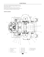
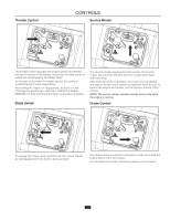
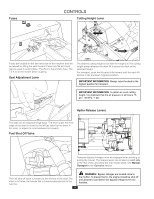
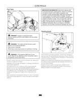
CONTROLS This operator manual describes the Husqvarna Zero Turn Rider. The rider is fitted with a Briggs & Stratton four-stroke overhead valve engine. Transmission from the engine is made via a belt-driven hydraulic pumps. Using the left and right steering controls, the flow is regulated and thereby the direction and speed. Control Locations 3 4 5 2 1 14 5 6 78 9 10 13 12 11 1. Motion control levers 2. Park brake 3. Tracking knob 4. Fuel tank 5. Hydro release levers 6. Choke control 7. Ignition switch 8. Service meter 9. Throttle control 10. Blade switch 11. Seat adjustment lever 11 12. Right tracking bolt 13. Cutting height lever 14. Deck lift pedal
-
 1
1 -
2
-
3
-
4
-
5
-
 6
6 -
 7
7 -
 8
8 -
 9
9 -
 10
10 -
 11
11 -
 12
12 -
 13
13 -
 14
14 -
 15
15 -
 16
16 -
17
-
18
-
19
-
20
-
21
-
22
-
23
-
24
-
25
-
26
-
27
-
28
-
29
-
30
-
31
-
32
-
33
-
34
-
35
-
36
-
37
-
38
-
39
-
40
-
41
-
42
-
43
-
44
 |
 |
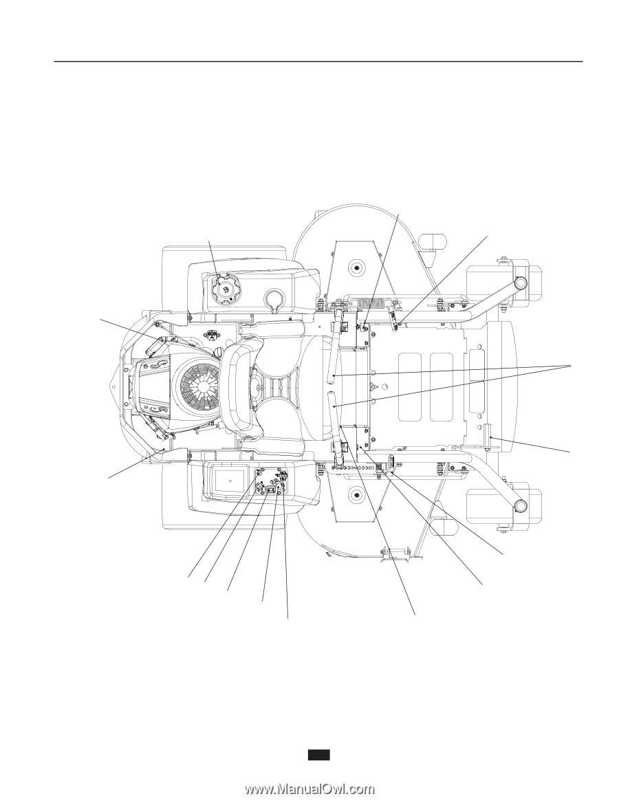
This operator manual describes the Husqvarna Zero Turn
Rider. The rider is fitted with a Briggs & Stratton four-stroke
overhead valve engine.
Transmission from the engine is made via a belt-driven
hydraulic pumps. Using the left and right steering controls, the
flow is regulated and thereby the direction and speed.
Control Locations
1.
Motion control levers
2.
Park brake
3.
Tracking knob
4.
Fuel tank
5.
Hydro release levers
6.
Choke control
7.
Ignition switch
8.
Service meter
9.
Throttle control
10. Blade switch
11. Seat adjustment lever
12. Right tracking bolt
13. Cutting height lever
14. Deck lift pedal
1
2
3
4
5
8
9
10
12
6
11
14
5
7
13
11
CONTROLS