Husqvarna YT54LS Owners Manual - Page 23
Service And Adjustments
 |
View all Husqvarna YT54LS manuals
Add to My Manuals
Save this manual to your list of manuals |
Page 23 highlights
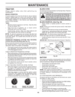
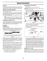
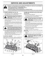
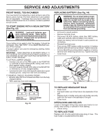
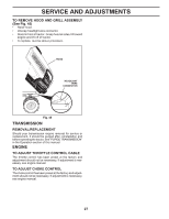
SERVICE AND ADJUSTMENTS WARNING: TO AVOID SERIOUS INJURY, BEFORE PERFORMING ANY SERVICE OR ADJUSTMENTS: • Depress brake pedal fully and set parking brake. • Place attachment clutch in "DISENGAGED" position. • Turn ignition key to "STOP" and remove key. • Make sure the blades and all moving parts have completely stopped. • Disconnect spark plug wire from spark plug and place wire where it cannot come in contact with plug. TO REMOVE MOWER (See Fig. 35) • Place attachment clutch in "DISENGAGED" position. • Lower attachment lift to its lowest position. • Disengage belt tension rod (K) from lock bracket (L). CAUTION: Belt tension rod is spring loaded. Have a tight grip on rod and release slowly. • Remove mower belt from electric clutch pulley (M). • Disconnect front link (E) from mower - remove retainer spring and washer. • Go to either side of mower and disconnect mower suspension arm (A) from chassis and rear lift link (C) from rear mower bracket (D) - remove retainer springs and washers. • Go to other side of mower and disconnect the suspension arm and rear lift link. CAUTION: After rear lift links are disconnected, the attachment lift lever will be spring loaded. Have a tight grip on lift lever when changing position of the lever. • From right side of mower, disconnect anti-sway bar (S) from right rear mower bracket (D) - remove retainer spring and washer and pull mower toward you until the bar falls from the hole in bracket. • Turn tractor steering wheel to the left as far as it will go. • Slide mower out from under right side of tractor. TO INSTALL MOWER Follow procedure described in "INSTALL MOWER AND DRIVE BELT" in the Assembly section of this manual. L K B M A F E H TO REPLACE MOWER BLADE DRIVE BELT (See Fig. 36) MOWER DRIVE BELT REMOVAL • Park tractor on a level surface. Engage parking brake. • Lower attachment lift to its lowest position. • Disengage belt tension rod (K) from lock bracket (L). CAUTION: Belt tension rod is spring loaded. Have a firm grip on rod and release slowly. • Remove screws (P) from mandrel covers (Q) and remove covers. • Remove any dirt or grass clippings which may have accumulated around mandrels and entire upper deck surface. • Remove belt from electric clutch pulley (M), both mandrel pulleys (R) and all idler pulleys (V). MOWER DRIVE BELT INSTALLATION • Install belt around all mandrel pulleys (R) and around idler pulleys (V) as shown. • Install belt onto electric clutch pulley (M). IMPORTANT: Check belt for proper routing in all mower pulley grooves. • Reassemble mandrel covers (Q). Securely tighten all screws. • Engage belt tension rod (K) on locking bracket (L). CAUTION: Belt tension rod is spring loaded. Have a tight grip on rod and engage slowly. • Raise attachment lift to highest position. P P L M P Q K R Q C DSC D Fig. 35 R 23 V R Fig. 36
-
 1
1 -
2
-
3
-
4
-
5
-
6
-
7
-
8
-
9
-
10
-
11
-
12
-
13
-
14
-
15
-
16
-
17
-
 18
18 -
 19
19 -
 20
20 -
 21
21 -
 22
22 -
 23
23 -
 24
24 -
 25
25 -
 26
26 -
 27
27 -
 28
28 -
29
-
30
-
31
-
32
-
33
-
34
-
35
-
36
-
37
-
38
-
39
-
40
-
41
-
42
-
43
-
44
-
45
-
46
-
47
-
48
-
49
-
50
-
51
-
52
-
53
-
54
-
55
-
56
-
57
-
58
-
59
-
60
-
61
-
62
-
63
-
64
-
65
-
66
-
67
-
68
-
69
-
70
-
71
-
72
 |
 |