Husqvarna YTH24V48LS Owners Manual - Page 20
Service And Adjustments - how to replace pulley
 |
View all Husqvarna YTH24V48LS manuals
Add to My Manuals
Save this manual to your list of manuals |
Page 20 highlights
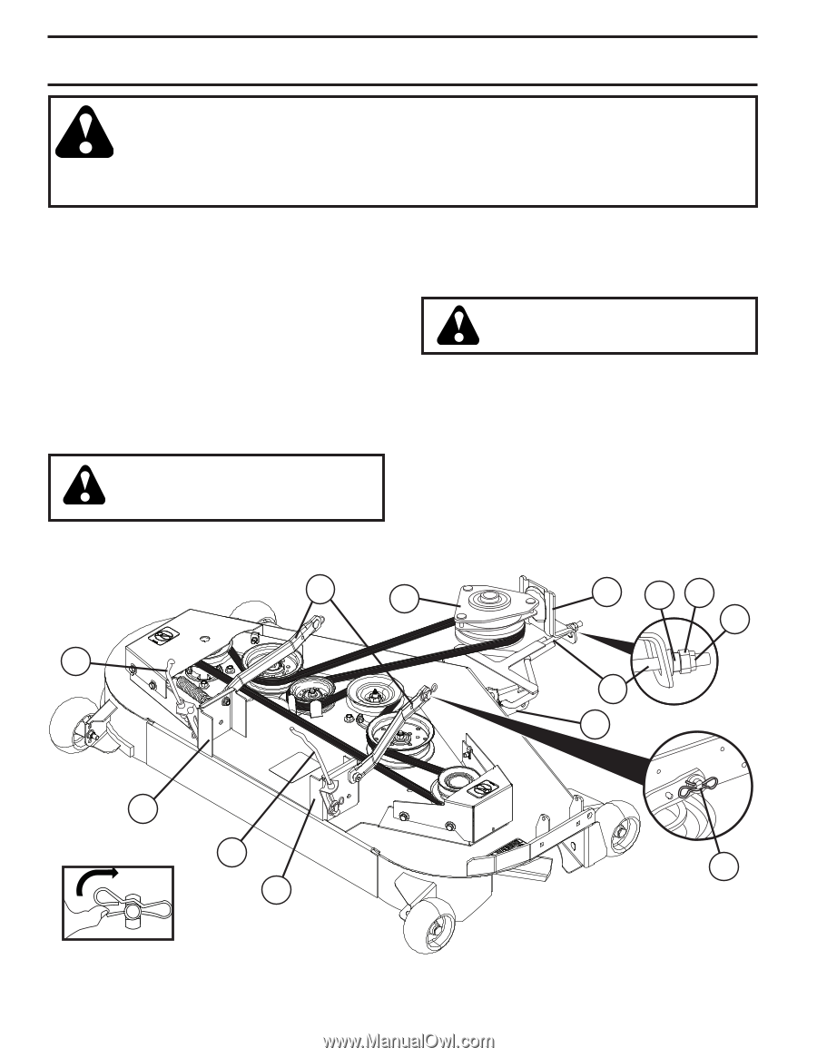
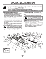
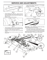
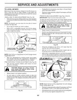
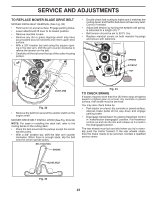
SERVICE AND ADJUSTMENTS WARNING: TO AVOID SERIOUS INJURY, BEFORE PERFORMING ANY SERVICE OR ADJUSTMENTS: • Depress brake pedal fully and set parking brake. • Place attachment clutch in "DISENGAGED" position. • Turn ignition key to "STOP" and remove key. • Make sure the blades and all moving parts have completely stopped. • Disconnect spark plug wire from spark plug and place wire where it cannot come in contact with plug. TO REMOVE MOWER (See Fig. 22) • Place attachment clutch in "DISENGAGED" position. • Lower attachment lift lever to its lowest position. • Remove mower belt from electric clutch pulley (M). See Mower Drive Belt Removal in "TO REPLACE MOWER BLADE DRIVE BELT" in this section. • Disconnect front link (E) from mower - remove retainer spring and washer. • Go to either side of mower and disconnect mower suspension arm (A) from chassis and rear lift link (C) from rear mower bracket (D) - remove retainer springs and washers. • Go to other side of mower and disconnect the suspension arm and rear lift link. CAUTION: After rear lift links are disconnected, the attachment lift lever will be spring loaded. Have a tight grip on lift lever when changing position of the lever. • Slide mower out from under right side of tractor. TO INSTALL MOWER (See Figs. 22 - 27) Be sure tractor is on level surface and engage parking brake. • Lower attachment lift lever to its lowest position. CAUTION: Lift lever is spring loaded. Have a tight grip on lift lever, lower it slowly and engage in lowest position. NOTE: Be sure mower side suspension arms (A) are pointing forward before sliding mower under tractor. • Slide mower under tractor until it is centered under tractor. • ATTACH MOWER SIDE SUSPENSION ARMS (A) TO CHASSIS - Position hole in arm over pin (B) on outside of tractor chassis and secure with retainer spring. • Repeat on opposite side of tractor. A M F OP Q C E H D C B D Fig. 22 20
-
 1
1 -
2
-
3
-
4
-
5
-
6
-
7
-
8
-
9
-
10
-
11
-
12
-
13
-
14
-
 15
15 -
 16
16 -
 17
17 -
 18
18 -
 19
19 -
 20
20 -
 21
21 -
 22
22 -
 23
23 -
 24
24 -
 25
25 -
26
-
27
-
28
-
29
-
30
-
31
-
32
-
33
-
34
-
35
-
36
-
37
-
38
-
39
-
40
-
41
-
42
-
43
-
44
 |
 |