IBM 2652 Hardware Maintenance Manual
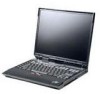
IBM 2652 - ThinkPad A31 - Pentium 4-M 1.9 GHz Manual
 |
UPC - 087944815198
View all IBM 2652 manuals
Add to My Manuals
Save this manual to your list of manuals |
IBM 2652 manual content summary:
- IBM 2652 | Hardware Maintenance Manual - Page 1
IBM Mobile Systems ThinkPad Computer Hardware Maintenance Manual September 2003 This manual supports: ThinkPad A30, A30p, A31, A31p (MT 2652/2653/2654) ThinkPad Dock (MT 2631) - IBM 2652 | Hardware Maintenance Manual - Page 2
Note Before using this information and the product it supports, be sure to read the general information under this publication may contain references to, or information about, IBM products (machines and programs), programming, or services that are not announced in your country. Such references or - IBM 2652 | Hardware Maintenance Manual - Page 3
27 Service web site 27 Restoring the preloaded system 27 Passwords 30 Power management 32 Checkout guide 36 Testing the computer 36 Detecting system information with PC-Doctor. . . 38 Power system checkout 39 ThinkPad A30, A30p, A31, A31p 43 Product overview 45 Specifications 45 - IBM 2652 | Hardware Maintenance Manual - Page 4
battery 75 1050 DIMM 76 1060 Hard-disk drive card 127 2030 LCD panel 129 2040 Antenna assembly 133 3010 ThinkPad Dock PCI cover 137 3020 ThinkPad Dock top cover 139 Locations 144 Front view 144 Rear view 146 Bottom view 147 Parts list 148 A30 and A30p series model matrix . . . . . 148 A31 - IBM 2652 | Hardware Maintenance Manual - Page 5
About this manual This manual contains service and reference information for IBM ThinkPad A30, A30p, A31, A31p (MT2652, 2653, 2654), and ThinkPad Dock (MT2631) products. Use this manual along with the advanced diagnostic tests to troubleshoot problems. The manual is divided into sections as follows: - IBM 2652 | Hardware Maintenance Manual - Page 6
2 MT 2652/2653/2654 - IBM 2652 | Hardware Maintenance Manual - Page 7
all diskette fixes are installed before replacing any FRUs listed in this manual. Use the following strategy to prevent unnecessary expense for replacing and servicing FRUs: v If you are instructed to replace a FRU but the replacement does not correct the problem, reinstall the original FRU before - IBM 2652 | Hardware Maintenance Manual - Page 8
information Strategy for replacing a hard-disk drive Always try to run a low-level format before replacing a hard-disk drive. Attention: The drive startup sequence in the computer you are servicing may have been changed. Be extremely careful during write operations such as copying, saving, or - IBM 2652 | Hardware Maintenance Manual - Page 9
Safety notice 1 Safety notices Before the computer is powered-on after FRU replacement, make sure all screws, springs, and other small parts are in place and are not left loose inside the computer. Verify this by shaking the - IBM 2652 | Hardware Maintenance Manual - Page 10
die Verkaufsstelle oder den IBM Kundendienst ausgetauscht werden. Sie darf nicht zerlegt, wiederaufgeladen, kurzgeschlossen, oder Feuer oder Wasser ausgesetzt werden. Die Batterie kann schwere Verbrennungen falscher Batterien kann zu Entzündung oder Explosion führen. (continued) 6 MT 2652/2653/2654 - IBM 2652 | Hardware Maintenance Manual - Page 11
(continuation of safety notice 2) Safety notices Alcune batterie di riserva contengono una piccola quantità di nichel e cadmio. Non smontarle, ricaricarle, gettarle nel fuoco o nell'acqua né cortocircuitarle. Smaltirle secondo la normativa in vigore (DPR - IBM 2652 | Hardware Maintenance Manual - Page 12
battery in the appropriate parts listing when replacing the battery pack. Use of an incorrect battery can result in ignition or explosion of the battery. La batterie remplacez la batterie, veillez à n'utiliser que les modèles quate. En effet, une batterie inappropriée risque de prendre der Batterie nur - IBM 2652 | Hardware Maintenance Manual - Page 13
Safety notices (continuation of safety notice 3) La batteria contiene piccole quantità di nichel. Non smontarla, gettarla nel fuoco o nell'acqua né cortocircuitarla. Smaltirla secondo la normativa in vigore (DPR 915/82, successive disposizioni e disposizioni locali). Quando si sostituisce la - IBM 2652 | Hardware Maintenance Manual - Page 14
battery as required by local ordinances or regulations. Use only the battery in the appropriate parts listing. Use of an incorrect battery can result in ignition or explosion of the battery Bestimmungen für Sondermüll beachten. Beim Ersetzen der Batterie nur Batterien des Typs verwenden, der in der - IBM 2652 | Hardware Maintenance Manual - Page 15
(continuation of safety notice 4) Safety notices La batteria di supporto e una batteria al litio e puo incendiarsi, esplodere o procurare gravi ustioni. Evitare di ricaricarla, smontarne il connettore polarizzato, smontarla, riscaldarla ad una temperatura superiore ai 100 gradi centigradi, - IBM 2652 | Hardware Maintenance Manual - Page 16
las áreas afectadas con agua durante 15 minutos como mínimo. Obtenga atención medica si se presenta algún síntoma del fluido despues de lavarse. 12 MT 2652/2653/2654 - IBM 2652 | Hardware Maintenance Manual - Page 17
Safety notice 6 DANGER Safety notices To avoid shock, do not remove the plastic cover that protects the lower part of the inverter card. Afin d'éviter tout risque de choc électrique, ne retirez pas le cache en plastique protégeant la partie inférieure de la carte d'alimentation. Aus - IBM 2652 | Hardware Maintenance Manual - Page 18
, um brennbare Materialien zu entzünden oder Verletzungen bei Personen hervorzurufen. Sebbene le batterie di alimentazione siano a basso voltaggio, una batteria in corto circuito o a massa suficiente como para quemar material combustible o provocar quemaduras en el personal. 14 MT 2652/2653/2654 - IBM 2652 | Hardware Maintenance Manual - Page 19
Safety notice 8 DANGER Safety notices Before removing any FRU, power off the computer, unplug all power cords from electrical outlets, remove the battery pack, and then disconnect any interconnecting cables. Avant de retirer une unité remplaçable en clientèle, mettez le système hors tension, dé - IBM 2652 | Hardware Maintenance Manual - Page 20
The following section presents the safety information that you need to be familiar with before servicing an IBM mobile computer. General safety Follow these rules to ensure general safety: v Observe good or working in any other conditions that might be hazardous to your eyes. 16 MT 2652/2653/2654 - IBM 2652 | Hardware Maintenance Manual - Page 21
Safety information v After service, reinstall all safety shields, guards, labels, and ground wires. Replace any safety device that is worn that contain small conductive fibers to decrease electrostatic discharges. Do not use this type of mat to protect yourself from electrical shock. v Find the room - IBM 2652 | Hardware Maintenance Manual - Page 22
very high voltages; these instructions are in the safety injury and machine damage. v Do not service the following parts with the power on when medical aid. Safety inspection guide The purpose of this inspection guide is to assist you in and service personnel from injury. This guide addresses only - IBM 2652 | Hardware Maintenance Manual - Page 23
first correcting the problem. Consider these conditions checklist at the beginning of every service task. Begin the checks with cord should be the type specified in the parts list. c. Insulation must not obvious non-IBM alterations. Use good judgment as to the safety of any non-IBM alterations. - IBM 2652 | Hardware Maintenance Manual - Page 24
especially useful when handling ESD-sensitive devices. v Select a grounding system, such as those listed below, to provide protection that meets the specific service requirement. Note The use of a grounding system is desirable but not required to protect against ESD damage. - Attach the ESD ground - IBM 2652 | Hardware Maintenance Manual - Page 25
Some IBM Personal Computer models are equipped from the factory with an optical storage device such as a CD-ROM drive or a DVD-ROM drive. They are also sold separately as options. The drive is certified in the U.S. to conform to the requirements of the Department of Health and Human Services 21 - IBM 2652 | Hardware Maintenance Manual - Page 26
o l'esecuzione di procedure diverse da quelle specificate possono provocare l'esposizione a. El uso de drive, DVD-ROM drive or the other optical storage device could result in exposure to hazardous laser radiation. There are no serviceable parts inside those drives. Do not open. 22 MT 2652 - IBM 2652 | Hardware Maintenance Manual - Page 27
Laser compliance statement Some CD-ROM drives, DVD-ROM drives, or other optical storage devices contain an embedded Class 3A or Class 3B laser diode. Note the following: DANGER Emits visible and invisible laser radiation - IBM 2652 | Hardware Maintenance Manual - Page 28
Laser compliance statement 24 MT 2652/2653/2654 - IBM 2652 | Hardware Maintenance Manual - Page 29
guide, be sure to read this section. Important notes v Only certified trained personnel should service the computer. v Read the entire FRU removal and replacement page before replacing discharge, or software errors. Consider replacing a FRU only when a problem recurs. If you suspect that a - IBM 2652 | Hardware Maintenance Manual - Page 30
password (making the computer unusable) v Sticky keys caused by spilling a liquid onto the keyboard The following symptoms might indicate damage caused by nonwarranted activities: v Missing parts might be a symptom of unauthorized service or modification. v If the spindle of a hard-disk drive - IBM 2652 | Hardware Maintenance Manual - Page 31
"Passwords" on page 30 v "Power management" on page 32 Service web site When the latest maintenance diskette and the system program service diskette become available, a notice will be posted on http://www.ibm.com/pc/partner/infotips Restoring the preloaded system If the data on a hard-disk drive is - IBM 2652 | Hardware Maintenance Manual - Page 32
the screen, select the operating system you want to recover. 5. Select the recovery options you want, and follow the instructions on the screen. 6. When the Product Recovery program finishes running, the computer will restart with the pre-installed operating system, drivers, and software. 28 MT 2652 - IBM 2652 | Hardware Maintenance Manual - Page 33
system, drivers, and software. Using the recovery CD To create the service partition and install the preloaded system from the recovery CD, do the following: To create the service partition: 1. Erase all partitions on the hard-disk drive, using FDISK or a similar application. 2. Boot with the - IBM 2652 | Hardware Maintenance Manual - Page 34
Recovery Repair diskette into the drive, and then turn on the computer. 3. Follow the on-screen instructions. Passwords As many as three passwords may be needed for any ThinkPad computer: the power-on password (POP), the hard-disk password (HDP), and the supervisor password (SVP). If any of these - IBM 2652 | Hardware Maintenance Manual - Page 35
available, IBM does not provide any services to reset either the user or the master HDP, or to recover data from the hard-disk drive. The hard-disk drive can be replaced for a scheduled fee. Supervisor password: A supervisor password (SVP) protects the system information stored in the IBM BIOS Setup - IBM 2652 | Hardware Maintenance Manual - Page 36
to remove the hard-disk password Attention: If User only mode is selected and the user HDP has been forgotten and cannot be made available to the servicer, IBM does not provide any services to reset the user HDPs or to recover data from the hard-disk drive. The hard-disk drive can be replaced for - IBM 2652 | Hardware Maintenance Manual - Page 37
service information v The hard-disk drive motor stops. 3. If the time set on the "Turn off monitor" timer in the operating system expires, v The LCD backlight turns off. To end screen are using the ACPI operating system, only the low-battery alarm is available. To cause the computer to return from - IBM 2652 | Hardware Maintenance Manual - Page 38
Related service information v Turn on the power switch. Also, the computer automatically returns from standby mode and resumes operation in either of the following events: v The ring indicator (RI) is signaled by a serial device or a PC Card device (Windows 2000 does not support the ring indicator ( - IBM 2652 | Hardware Maintenance Manual - Page 39
have set the mode to Hibernate when battery becomes low, and the battery charge becomes critically low. When the power is turned on, the computer returns from hibernation mode and resumes operation. The hibernation file in the boot record on the hard-disk drive is read, and system status is restored - IBM 2652 | Hardware Maintenance Manual - Page 40
Use the following procedures as a guide in identifying and correcting problems with the ThinkPad computer. Note: The diagnostic tests are intended to test only IBM products. The use of non-IBM products, prototype cards, or modified options can lead to false indications of errors and invalid system - IBM 2652 | Hardware Maintenance Manual - Page 41
Adapter v Serial Ports v Parallel Ports v Fixed Disks v Diskette Drives v Other Devices v ZIP Drive v LS-120/240 Drive v Communication v Wireless LAN v Memory Test - Full v Memory Test - Quick Interactive Tests v Keyboard v Video v Internal Speaker v Mouse v Diskette v System Load v CD-ROM/DVD - IBM 2652 | Hardware Maintenance Manual - Page 42
IDE Drive Info v PCI Information v PNPISA Info v SMBIOS Info v VESA LCD Info Utility v Run External Tests v Surface Scan Hard Disk v Benchmark System v DOS Shell v Tech Support Form v Battery Rundown v View Test Log v Print Log v Save Log v Full Erase Hard Drive v Quick Erase Hard Drive 38 MT 2652 - IBM 2652 | Hardware Maintenance Manual - Page 43
on page 40 v "Checking the battery pack" on page 40 v "Checking the backup battery" on page 41 Checking the ac adapter You are here because the computer fails only when the ac adapter is used: v If the power problem occurs only when the port replicator is used, replace the port replicator. v If the - IBM 2652 | Hardware Maintenance Manual - Page 44
pack and let it return to room temperature. Reinstall the battery pack. If the charge indicator or icon still does not turn on, replace the battery pack. If the charge indicator still does not turn on, replace the system board. Then reinstall the battery pack. If it is still not charged, go to the - IBM 2652 | Hardware Maintenance Manual - Page 45
Checkout guide Note: Recharging will take at least 3 hours, even if the indicator does not turn on. If the voltage is still less than +11.0 V dc after recharging, replace the battery. 4. If the voltage is more than +11.0 V dc, measure the resistance between battery terminals 4 and 5. The resistance - IBM 2652 | Hardware Maintenance Manual - Page 46
Checkout guide 42 MT 2652/2653/2654 - IBM 2652 | Hardware Maintenance Manual - Page 47
UUID 61 Removing and replacing a FRU 63 1010 Battery pack 64 1020 Mini PCI adapter 65 1030 Communication daughter card (CDC) . . . 68 Ethernet daughter card 69 Modem daughter card 71 Bluetooth daughter card 73 1040 Backup battery 75 1050 DIMM 76 1060 Hard-disk drive 77 1070 Ultrabay Plus - IBM 2652 | Hardware Maintenance Manual - Page 48
XP professional (A30/A30p) For Windows 2000 (A31/A31p) . . . . For Windows XP professional (A31/A31p) For Windows XP Home Edition (A31/A31p) Optional FRUs Ultrabay devices Other optional FRUs Miscellaneous parts AC adapters Common parts list Tools Power cords (system Power cords (ThinkPad - IBM 2652 | Hardware Maintenance Manual - Page 49
Specifications The following table lists the specifications of the ThinkPad A3* series: Feature Processor Bus architecture Internal modem Description A30 Mobile Intel® Pentium® 4 processor 2.0 GHz A30, A30p v 133 MHz PSB v HUB Link v PCI Bus v LPC Bus v 133 MHz SDRAM A31, A31p v 400 MHz PSB v HUB - IBM 2652 | Hardware Maintenance Manual - Page 50
) v 64 MB DDR SDRAM (on the system board) CMOS RAM 242 bytes Hard-disk drive MT2652 and MT2654 (A30) v 20.0 GB, 2.5-inch, IDE interface v 30.0 GB, 2.5-inch, IDE interface MT2653 (A30p) v 48.0 GB, 2.5-inch, IDE interface MT2652 and MT2654 (A31) v 20.0 GB, 2.5-inch, IDE interface v 30.0 GB, 2.5-inch - IBM 2652 | Hardware Maintenance Manual - Page 51
DVD-ROM drive v DVD/CD-RW combo drive UltraPort device (option only for A30p, A31p) Preinstalled operating system MT2653 (A31p) v DVD/CD-RW combo drive v UltraPort camera v Bluetooth UltraPort module v Windows XP Professional v Windows 2000 v Windows XP Home Edition ThinkPad A30, A30p, A31, A31p - IBM 2652 | Hardware Maintenance Manual - Page 52
9 87654 Indicator 1 Bluetooth status 2 Battery status Meaning Green: The Bluetooth is battery is in use and has enough power. The ac adapter has charged the battery completely. Blinking green: The battery battery is being charged, but the battery power is still low. Blinking orange: The battery - IBM 2652 | Hardware Maintenance Manual - Page 53
used as screen-scroll function keys. The cursor cannot be moved with the Arrow keys. Not all application programs support this function key. 8 Drive in use Green: Data is being read from or written to the hard-disk drive, the diskette drive, or the drive in the ThinkPad A30, A30p, A31, A31p 49 - IBM 2652 | Hardware Maintenance Manual - Page 54
Modem Audio Speaker PC Card slots Keyboard Memory Diskette drive Hard-disk drive Applicable test 1. Diagnostics --> CPU/Coprocessor 2. Diagnostics --> Systemboard Diagnostics --> Other Devices --> IBM AC Adapter, IBM Battery 1 (IBM Battery 2) 1. Diagnostics --> Video Adapter 2. Interactive Tests - IBM 2652 | Hardware Maintenance Manual - Page 55
screen for a short time. This drift can occur when a slight, steady pressure is applied to the TrackPoint pointer. This symptom is not a hardware problem. If the pointer stops after a short time, no service action is necessary. CD-ROM or DVD drive down. (continued) ThinkPad A30, A30p, A31, A31p 51 - IBM 2652 | Hardware Maintenance Manual - Page 56
function is not supported in Windows 2000. Fn+F9 Reserved. Fn+F10 Reserved. Fn+F11 Reserved. Fn+F12 Turn hibernation mode on. To return to normal operation, press the power button for less than four seconds. Note: To use Fn+F12 for hibernation in Windows 2000, IBM PM device driver must have - IBM 2652 | Hardware Maintenance Manual - Page 57
descriptions of symptoms. If the symptom is not described there, go to "Intermittent problems" on page 59. Note For an IBM device not supported by diagnostic codes in the ThinkPad notebook computers, see the manual for that device. Numeric error codes Symptom or error FRU or action, in sequence - IBM 2652 | Hardware Maintenance Manual - Page 58
BIOS Setup System Security-IBM Security password retry count exceeded. Utility, and then save current setting by pressing F10. 2. System board. 01C8 More than one modem devices are found. Remove one of them. Press to continue. 1. Remove either a Mini PCI modem card or an modem daughter - IBM 2652 | Hardware Maintenance Manual - Page 59
Real time clock error 1. Replace the backup battery and run IBM BIOS Setup Utility to reset the time and date. 2. System board. 0271 Date and time error-Neither the date nor the time is set in the computer. Run IBM BIOS Setup Utility to reset the time and date. ThinkPad A30, A30p, A31, A31p 55 - IBM 2652 | Hardware Maintenance Manual - Page 60
02B2 Incorrect drive A type 02F4 EISA CMOS not writable 02F5 DMA test failed 02F6 Software NMI failed 02F7 Fail-safe timer NMI failed FRU or action, in sequence 1. Diskette drive. 2. External FDD cable. 3. I/O card. 1. Load Setup Defaults in IBM BIOS Setup Utility. 2. Replace the backup battery - IBM 2652 | Hardware Maintenance Manual - Page 61
to what it was before the computer entered hibernation mode. 2. If memory size has been changed, re-create the hibernation file. Fan. System board System board (IBM security and a blank screen. chip) Five short beeps and a blank screen. System board ThinkPad A30, A30p, A31, A31p 57 - IBM 2652 | Hardware Maintenance Manual - Page 62
TFT LCD technology, but excessive pixel problems can cause viewing concerns. The LCD should be replaced if the number of missing, LCD brightness cannot be adjusted. v LCD screen unreadable. v Characters missing pixels. v Screen abnormal. v Wrong color displayed. Horizontal . 58 MT 2652/2653/2654 - IBM 2652 | Hardware Maintenance Manual - Page 63
: a. Non-IBM devices b. Devices attached to the port replicator c. Printer, mouse, and other external devices d. Battery pack e. Hard-disk drive f. External diskette drive g. DIMM h. CD-ROM and diskette drive in the Ultrabay i. PC Cards 4. Power on the computer. 5. Determine whether the problem has - IBM 2652 | Hardware Maintenance Manual - Page 64
notices This section contains notices related to removing and replacing parts. Read this section carefully before replacing any FRU. Screw notices Loose screws can cause a reliability problem. In IBM ThinkPad computer, this problem is addressed with special nylon-coated screws that have the - IBM 2652 | Hardware Maintenance Manual - Page 65
the instructions on the screen. Note: The serial number of the system unit is written on the label attached on the bottom of the computer. Retaining the UUID The Universally Unique Identifier (UUID) is a 128-bit number uniquely assigned to your computer at production ThinkPad A30, A30p, A31, A31p - IBM 2652 | Hardware Maintenance Manual - Page 66
the year A.D. 3400. No two computers in the world have the same number. When you replace the system board, you must set the UUID on the new system board as follows: 1. Install the ThinkPad Hardware Maintenance Diskette Version 1.62, and restart the computer. 2. From the main menu, select 4. Assign - IBM 2652 | Hardware Maintenance Manual - Page 67
cords from electrical outlets, remove the battery pack, and then disconnect any interconnecting cables. Attention: Before the computer is powered on after FRU replacement, make sure that all screws, by using an electrostatic discharge (ESD) strap (P/N 6405959). ThinkPad A30, A30p, A31, A31p 63 - IBM 2652 | Hardware Maintenance Manual - Page 68
Removing and replacing a FRU 1010 Battery pack DANGER The use only the battery in the parts listing for your computer. Use of an incorrect battery can result in ignition or explosion of the battery. 1 2 64 MT 2652/2653/2654 - IBM 2652 | Hardware Maintenance Manual - Page 69
Removing and replacing a FRU 1020 Mini PCI adapter For access, remove this FRU: v "1010 Battery pack" on page 64 Note: Loosen the screws 1 , but do not remove them. 1 2 1 (continued) ThinkPad A30, A30p, A31, A31p 65 - IBM 2652 | Hardware Maintenance Manual - Page 70
illustrations show the wireless LAN/modem combo card. Antenna cables 3a and 3b are for the wireless LAN feature, and 6 is for the modem feature. This slot also supports a Mini PCI modem card. Note: When unplugging the tab marked "AUX" ( 3b ) into jack J2. 4 5 5 (continued) 66 MT 2652/2653/2654 - IBM 2652 | Hardware Maintenance Manual - Page 71
and replacing a FRU 7 6 When installing: With the notched end of the card toward the socket, insert the card into the socket, and then press it firmly. Pivot the card until it snaps into place. Make sure that the card is firmly fixed in the slot and does not move easily. ThinkPad A30, A30p, A31 - IBM 2652 | Hardware Maintenance Manual - Page 72
Removing and replacing a FRU 1030 Communication daughter card (CDC) For access, remove this FRU: v "1010 Battery pack" on page 64 Note: Loosen the screws 1 , but do not remove them. 1 2 1 (continued) 68 MT 2652/2653/2654 - IBM 2652 | Hardware Maintenance Manual - Page 73
card Following illustrations show the combination of the MiniPCI combo (modem/wireless LAN) card and Ethernet daughter card. 3 3 4 Step 3 Screw (quantity) CDC screw (2) 5 6 Torque 0.392 Nm (4 kgfcm) When installing: Make sure that connectors 4 and 6 are firmly attached. ThinkPad A30, A30p, A31 - IBM 2652 | Hardware Maintenance Manual - Page 74
Removing and replacing a FRU Cable routing: When attaching the Ethernet daughter card, route the cable as this figure. 70 MT 2652/2653/2654 - IBM 2652 | Hardware Maintenance Manual - Page 75
replacing a FRU Modem daughter card Following illustrations show the combination of the Ethernet daughter card and Modem daughter card. 3 3 4 Step 3 Screw (quantity) CDC screw (2) 5 Torque 0.392 Nm (4 kgfcm) When installing: Make sure that connectors 4 and 6 are firmly attached. ThinkPad A30 - IBM 2652 | Hardware Maintenance Manual - Page 76
Removing and replacing a FRU Cable routing: When attaching the Modem daughter card, route the cable as this figure. 72 MT 2652/2653/2654 - IBM 2652 | Hardware Maintenance Manual - Page 77
Bluetooth daughter card. 3 3 4 Step 3 Screw (quantity) CDC screw (2) Torque 0.392 Nm (4 kgfcm) 6 5 When installing: 1. Make sure that the connector 4 is firmly attached. 2. Plug the white cable with the tab marked "BT" into the jack on the Bluetooth daughter card. ThinkPad A30, A30p, A31, A31p - IBM 2652 | Hardware Maintenance Manual - Page 78
Removing and replacing a FRU Cable routing: When attaching the Bluetooth daughter card, route the cable as this figure. 74 MT 2652/2653/2654 - IBM 2652 | Hardware Maintenance Manual - Page 79
only the battery in the parts listing for your computer. Use of an incorrect battery can result in ignition or explosion of the battery. For access, remove these FRUs, in order: v "1010 Battery pack" on page 64 v "1030 Communication daughter card (CDC)" on page 68 1 2 ThinkPad A30, A30p, A31, A31p - IBM 2652 | Hardware Maintenance Manual - Page 80
Removing and replacing a FRU 1050 DIMM For access, remove this FRU: v "1010 Battery pack" on page 64 Note: Loosen the screws 1 , but do not remove them. 2 1 The it firmly. Pivot the DIMM until it snaps into place. Make sure that the card is firmly fixed in the slot and does not move easily. 76 MT - IBM 2652 | Hardware Maintenance Manual - Page 81
in suspend mode. For access, remove this FRU: v "1010 Battery pack" on page 64 1 Note: The hard disk is attached to the cover. Step Screw (quantity) 1 HDD screw (1) or security screw (1) Note: Use a 2.5-mm Allen wrench to remove the security screw. (continued) ThinkPad A30, A30p, A31, A31p 77 - IBM 2652 | Hardware Maintenance Manual - Page 82
Removing and replacing a FRU 2 3 4 3 When installing: Make sure that the hard-disk connector is firmly connected. 78 MT 2652/2653/2654 - IBM 2652 | Hardware Maintenance Manual - Page 83
battery. For supported devices, see "Optional FRUs" on page 179. The procedure for installing and removing is the same for every device. Note: When you release the switch in step 1 the lever pops out. Pull the lever a little in step 2 to release the device from the bay. 3 1 2 ThinkPad A30, A30p, A31 - IBM 2652 | Hardware Maintenance Manual - Page 84
devices. For supported devices, see "Optional FRUs" on page 179. The procedure for installing and removing is the same for every device. Note: When you release the switch in step 1 the lever pops out. Pull the lever a little in step 2 to release the device from the bay. 3 1 2 80 MT 2652/2653/2654 - IBM 2652 | Hardware Maintenance Manual - Page 85
1090 I/O plate Removing and replacing a FRU For access, remove this FRU: v "1010 Battery pack" on page 64 2 1 2 1 1 Step 1 Screw (quantity) Hex stud (6) Torque 0.392 Nm (4 kgfcm) ThinkPad A30, A30p, A31, A31p 81 - IBM 2652 | Hardware Maintenance Manual - Page 86
Removing and replacing a FRU 1100 Keyboard For access, remove these FRUs, in order: v "1010 Battery pack" on page 64 v "1070 Ultrabay Plus device" on page 79 v "1080 Ultrabay 2000 device" on page 80 1 Step 1 Screw (quantity) M2.5 × 16 mm, nylon- - IBM 2652 | Hardware Maintenance Manual - Page 87
Removing and replacing a FRU In step 5 , open the keyboard slightly in the direction of the arrow. 5 4 In step 6 , draw the keyboard a little in the direction of the arrow, and then detach the connector 7 . 7 6 ThinkPad A30, A30p, A31, A31p 83 - IBM 2652 | Hardware Maintenance Manual - Page 88
Removing and replacing a FRU Before installing the keyboard Some keyboard CRU insulators are not fixed with an adhesive tape and are easily moved. For those as in following figure. If the keyboard CRU insulator is not placed firmly, the keyboard cannot be installed properly. 84 MT 2652/2653/2654 - IBM 2652 | Hardware Maintenance Manual - Page 89
Removing and replacing a FRU When installing: Install the new keyboard, following the directions below. 1. Attach the connector. 2. Make sure that the keyboard edges, shown in the figure as (A) and (B), are under the frame. (B) (A) (continued) ThinkPad A30, A30p, A31, A31p 85 - IBM 2652 | Hardware Maintenance Manual - Page 90
Removing and replacing a FRU 3. Press the keys indicated by arrows to latch the try to slide the keyboard towards you. Do not push hard on parts (A) and (B) on the keyboard; to do so might distort the Ultrabay slots. (A) (B) 5. Replace the screws, using the new screws provided with the keyboard. - IBM 2652 | Hardware Maintenance Manual - Page 91
v "1010 Battery pack" on page 64 v "1070 Ultrabay Plus device" on page 79 v "1080 Ultrabay 2000 device" on page 80 v "1100 Keyboard" on page 82 Keyboard CRU insulator 1 is fixed with an adhesive tape. 1 Keyboard CRU insulator 1a is not fixed with an adhesive tape. 1a ThinkPad A30, A30p, A31, A31p 87 - IBM 2652 | Hardware Maintenance Manual - Page 92
Removing and replacing a FRU When installing: Some keyboard CRU insulators are not fixed with an adhesive tape and are easily moved. For those insulators, make as in following figure. If the keyboard CRU insulator is not placed firmly, the keyboard cannot be installed properly. 88 MT 2652/2653/2654 - IBM 2652 | Hardware Maintenance Manual - Page 93
Battery pack" on page 64 v "1070 Ultrabay Plus device" on page 79 v "1080 Ultrabay 2000 device" on page 80 v "1100 Keyboard" on page 82 v "1110 Keyboard CRU insulator" on page 87 1 1 1 1 Step 1 Screw (quantity) M2.5 × 16 mm, nylon-coated (4) (continued) Torque 0.392 Nm (4 kgfcm) ThinkPad A30 - IBM 2652 | Hardware Maintenance Manual - Page 94
Removing and replacing a FRU 2 Step 2 Screw (quantity) M2 × 15 mm, nylon-coated (1) (continued) Torque 0.245 Nm (2.5 kgfcm) 90 MT 2652/2653/2654 - IBM 2652 | Hardware Maintenance Manual - Page 95
3 4 Removing and replacing a FRU 3 Step 3 Screw (quantity) M2.5 × 4.8 mm, nylon-coated (2) 4 M2.5 × 19.5 mm, nylon-coated (1) Torque 0.392 Nm (4 ( a ) on the front side of the computer are detached, and then remove the keyboard bezel. 6 5 a a a a a ThinkPad A30, A30p, A31, A31p 91 - IBM 2652 | Hardware Maintenance Manual - Page 96
Removing and replacing a FRU When installing the keyboard bezel, do the following: 1. Attach the keyboard bezel to the computer, aligning two dents of the bezel attached. 3. Make sure that both the left and right latches on the bottom side of the bezel are firmly attached. 92 MT 2652/2653/2654 - IBM 2652 | Hardware Maintenance Manual - Page 97
1130 Hinge cover Removing and replacing a FRU For access, remove these FRUs, in order: v "1010 Battery pack" on page 64 v "1070 Ultrabay Plus device" on page 79 v "1080 Ultrabay 2000 device" on the rear side with the two small square holes of the base cover. (a) ThinkPad A30, A30p, A31, A31p 93 - IBM 2652 | Hardware Maintenance Manual - Page 98
replacing a FRU 1140 Fan assembly For access, remove these FRUs, in order: v "1010 Battery pack" on page 64 v "1030 Communication daughter card (CDC)" on page 68 v "1040 Backup battery" on page 75 v "1060 Hard-disk drive the bracket and the fan assembly firmly. (continued) 94 MT 2652/2653/2654 - IBM 2652 | Hardware Maintenance Manual - Page 99
Removing and replacing a FRU 4 5 When installing: Make sure that the connector 5 is firmly attached. Note Apply thermal grease on the a -part of the fan, shown in the following figure. a ThinkPad A30, A30p, A31, A31p 95 - IBM 2652 | Hardware Maintenance Manual - Page 100
replacing a FRU 1150 CPU For access, remove these FRUs, in order: v "1010 Battery pack" on page 64 v "1030 Communication daughter card (CDC)" on page 68 v "1040 Backup battery" on page 75 v "1060 Hard-disk drive Note: There are two types of CPU socket. Confirm the socket type of the computer first. - IBM 2652 | Hardware Maintenance Manual - Page 101
Removing and replacing a FRU When installing: Place the CPU on the CPU socket ( 1 ), and then rotate the head of the screw (A) in the direction of arrow 2 to lock the CPU. 2 1 A A' 1' 2' ThinkPad A30, A30p, A31, A31p 97 - IBM 2652 | Hardware Maintenance Manual - Page 102
replacing a FRU 1160 Ultrabay Plus slot For access, remove these FRUs, in order: v "1010 Battery pack" on page 64 v "1030 Communication daughter card (CDC)" on page 68 v "1040 Backup battery" on page 75 v "1060 Hard-disk drive -coated (2) (continued) Torque 0.392 Nm (4 kgfcm) 98 MT 2652/2653/2654 - IBM 2652 | Hardware Maintenance Manual - Page 103
Removing and replacing a FRU 4 3 53 Step 3 Screw (quantity) M2.5 × 16 mm, nylon-coated (2) 4 M2.5 × 4.8 mm, nylon-coated (1) (continued) Torque 0.392 Nm (4 kgfcm) 0.392 Nm (4 kgfcm) ThinkPad A30, A30p, A31, A31p 99 - IBM 2652 | Hardware Maintenance Manual - Page 104
Removing and replacing a FRU 6 6 Step 6 Screw (quantity) M2.5 × 4.8 mm, nylon-coated (4) (continued) Torque 0.392 Nm (4 kgfcm) 100 MT 2652/2653/2654 - IBM 2652 | Hardware Maintenance Manual - Page 105
Removing and replacing a FRU The Ultrabay release lever pops out ( 8 ) when the bay slot is slightly lifted as in step 7 . 7 8 a When installing: cover, slide the Ultrabay latch knob toward you until it snaps ( a ). Then attach the bay to the computer. (continued) ThinkPad A30, A30p, A31, A31p 101 - IBM 2652 | Hardware Maintenance Manual - Page 106
Removing and replacing a FRU Detach the bay slot in the direction of arrow 10 , avoid damaging the Ultrabay release lever 9 . 10 9 102 MT 2652/2653/2654 - IBM 2652 | Hardware Maintenance Manual - Page 107
replacing a FRU 1170 Ultrabay 2000 slot For access, remove these FRUs, in order: v "1010 Battery pack" on page 64 v "1030 Communication daughter card (CDC)" on page 68 v "1040 Backup battery" on page 75 v "1060 Hard-disk drive (continued) Torque 0.392 Nm (4 kgfcm) ThinkPad A30, A30p, A31, A31p 103 - IBM 2652 | Hardware Maintenance Manual - Page 108
Removing and replacing a FRU 4 (a) 3 4 (b) 4 (c) 5 Step 3 Screw (quantity) M2.5 × 4.8 mm, nylon-coated (1) 4 M2 × 15 mm, nylon-coated (3) Torque 0.392 Nm (4 kgfcm of (a), (b), and (c). 3. Tighten the screw 3 to secure the bracket and the fan assembly firmly. (continued) 104 MT 2652/2653/2654 - IBM 2652 | Hardware Maintenance Manual - Page 109
6 6 6 Removing and replacing a FRU Step 6 Screw (quantity) M2.5 × 4.8 mm, nylon-coated (3) (continued) Torque 0.392 Nm (4 kgfcm) ThinkPad A30, A30p, A31, A31p 105 - IBM 2652 | Hardware Maintenance Manual - Page 110
Removing and replacing a FRU The Ultrabay release lever pops out ( 8 ) when the bay slot is slightly lifted as in step 7 . a 7 8 When installing: After inserting . Detach the bay slot to the direction of arrow 10 , to avoid damaging the Ultrabay release lever 9 . 9 10 106 MT 2652/2653/2654 - IBM 2652 | Hardware Maintenance Manual - Page 111
replacing a FRU 1180 Sub card for PC Card slot For access, remove these FRUs, in order: v "1010 Battery pack" on page 64 v "1030 Communication daughter card (CDC)" on page 68 v "1040 Backup battery" on page 75 v "1060 Hard-disk drive ) Torque 0.245 Nm (2.5 kgfcm) ThinkPad A30, A30p, A31, A31p 107 - IBM 2652 | Hardware Maintenance Manual - Page 112
Removing and replacing a FRU 2 3 Step 2 Screw (quantity) M2 × 15 mm, nylon-coated (1) Torque 0.245 Nm (2.5 kgfcm) 108 MT 2652/2653/2654 - IBM 2652 | Hardware Maintenance Manual - Page 113
replacing a FRU Note Some ThinkPad computers may have an embedded security chip, which the customer ordered as an option. If the ThinkPad computer you are servicing Communication daughter card (CDC)" on page 68 v "1040 Backup battery" on page 75 v "1050 DIMM" on page 76 v "1060 Hard-disk drive" on - IBM 2652 | Hardware Maintenance Manual - Page 114
replacing a FRU 1200 LCD assembly For access, remove these FRUs, in order: v "1010 Battery pack" on page 64 v "1020 Mini PCI adapter" on page 65 v "1030 Communication daughter card (CDC)" on page 68 v "1040 Backup battery" on page 75 v "1060 Hard-disk drive 0.392 Nm (4 kgfcm) 110 MT 2652/2653/2654 - IBM 2652 | Hardware Maintenance Manual - Page 115
Removing and replacing a FRU 2 When installing: Make sure that the connector 2 is firmly attached. (continued) ThinkPad A30, A30p, A31, A31p 111 - IBM 2652 | Hardware Maintenance Manual - Page 116
Removing and replacing a FRU 3 3 112 MT 2652/2653/2654 - IBM 2652 | Hardware Maintenance Manual - Page 117
replacing a FRU Installation notice for the model with the wireless LAN feature Some models have cables for the wireless LAN antenna. After you attach the LCD assembly, route the antenna cables as shown in the following figure, and secure the cables with new insulation tapes. ThinkPad A30, A30p, A31 - IBM 2652 | Hardware Maintenance Manual - Page 118
Removing and replacing a FRU 1210 System board For access, remove these FRUs, in order: v "1010 Battery pack" on page 64 v "1020 Mini PCI adapter" on page 65 v "1030 Communication daughter card (CDC)" on page 68 v "1040 Backup battery" on page 75 v "1050 DIMM" on page 76 v "1060 Hard-disk drive" on - IBM 2652 | Hardware Maintenance Manual - Page 119
Removing and replacing a FRU 1 1 Step 1 Screw (quantity) M2.5 × 4.8 mm Small head, nylon-coated (4) (continued) Torque 0.254 Nm (2.5 kgfcm) ThinkPad A30, A30p, A31, A31p 115 - IBM 2652 | Hardware Maintenance Manual - Page 120
Removing and replacing a FRU 2 3 Step 2 Screw (quantity) M2.5 × 4.8 mm, nylon-coated (1) (continued) Torque 0.392 Nm (4 kgfcm) 116 MT 2652/2653/2654 - IBM 2652 | Hardware Maintenance Manual - Page 121
Removing and replacing a FRU a 4 5 When installing: Do as shown in figure a . 6 Step 6 Screw (quantity) M2.5 × 4.8 mm, nylon-coated (1) (continued) Torque 0.392 Nm (4 kgfcm) ThinkPad A30, A30p, A31, A31p 117 - IBM 2652 | Hardware Maintenance Manual - Page 122
Removing and replacing a FRU 8 8 7 When installing: Make sure that both of the connectors are firmly attached. 9 When installing: Attach the system board so that the two small projections on the base cover fit into the holes provided. (continued) 118 MT 2652/2653/2654 - IBM 2652 | Hardware Maintenance Manual - Page 123
Removing and replacing a FRU 13 12 When installing: Make sure that the Ethernet/modem cable is firmly attached to two connectors on the bottom of the system board. And then, stick the EMI tape to secure the cable on the system board. ThinkPad A30, A30p, A31, A31p 119 - IBM 2652 | Hardware Maintenance Manual - Page 124
and replacing a FRU 1220 Ultrabay LED card For access, remove these FRUs, in order: v "1010 Battery pack" on page 64 v "1020 Mini PCI adapter" on page 65 v "1030 Communication daughter card (CDC)" on page 68 v "1040 Backup battery" on page 75 v "1050 DIMM" on page 76 v "1060 Hard-disk drive" on - IBM 2652 | Hardware Maintenance Manual - Page 125
and replacing a FRU 1230 Speaker assembly For access, remove these FRUs, in order: v "1010 Battery pack" on page 64 v "1020 Mini PCI adapter" on page 65 v "1030 Communication daughter card (CDC)" on page 68 v "1040 Backup battery" on page 75 v "1050 DIMM" on page 76 v "1060 Hard-disk drive" on - IBM 2652 | Hardware Maintenance Manual - Page 126
Removing and replacing a FRU 2 2 3 3 Step 2 Screw (quantity) M2.5 × 4.8 mm, nylon-coated (2) Torque 0.392 Nm (4 kgfcm) 122 MT 2652/2653/2654 - IBM 2652 | Hardware Maintenance Manual - Page 127
Some ThinkPad computers may not have this FRU. For access, remove these FRUs, in order: v "1010 Battery pack" on page 64 v "1020 Mini PCI adapter" on page 65 v "1030 Communication daughter card (CDC)" on page 68 v "1040 Backup battery" on page 75 v "1050 DIMM" on page 76 v "1060 Hard-disk drive" on - IBM 2652 | Hardware Maintenance Manual - Page 128
Removing and replacing a FRU Cable routing: When attaching the antenna for Bluetooth, route the cable to fit into the cable guides on the base cover. 124 MT 2652/2653/2654 - IBM 2652 | Hardware Maintenance Manual - Page 129
replacing a FRU For access, remove these FRUs, in order: v "1010 Battery pack" on page 64 v "1020 Mini PCI adapter" on page 65 v "1030 Communication daughter card (CDC)" on page 68 v "1040 Backup battery" on page 75 v "1060 Hard-disk drive Torque 0.392 Nm (4 kgfcm) ThinkPad A30, A30p, A31, A31p 125 - IBM 2652 | Hardware Maintenance Manual - Page 130
replaced to with a new one, clear plate set must also be installed. The procedure is as follows: 1. There are several clear plates in the clear plate set. Confirm the model name, such as "A30" first, and pick the plate suitable for the computer you are servicing . a 1 2 2 1 126 MT 2652/2653/2654 - IBM 2652 | Hardware Maintenance Manual - Page 131
2020 Inverter card Removing and replacing a FRU For access, remove these FRUs, in order: v "1010 Battery pack" on page 64 v "1020 Mini PCI adapter" on page 65 v "1030 Communication daughter card (CDC)" on page 68 v "1040 Backup battery" on page 75 v "1060 Hard-disk drive" on page 77 v "1070 - IBM 2652 | Hardware Maintenance Manual - Page 132
Removing and replacing a FRU Cable routing: When replacing the inverter card, route the connector cable as in the following figure: 128 MT 2652/2653/2654 - IBM 2652 | Hardware Maintenance Manual - Page 133
replacing a FRU For access, remove these FRUs, in order: v "1010 Battery pack" on page 64 v "1020 Mini PCI adapter" on page 65 v "1030 Communication daughter card (CDC)" on page 68 v "1040 Backup battery" on page 75 v "1060 Hard-disk drive "2020 Inverter card" on ThinkPad A30, A30p, A31, A31p 129 - IBM 2652 | Hardware Maintenance Manual - Page 134
Removing and replacing a FRU 2 2 Step 2 Screw (quantity) M2 × 5.7 mm, nylon-coated (4) Torque 0.245 Nm (2.5 kgfcm) 4 3 (continued) 130 MT 2652/2653/2654 - IBM 2652 | Hardware Maintenance Manual - Page 135
For 14.1-in. LCD panel 8 Removing and replacing a FRU 5 6 7 8 Step 8 Screw (quantity) M2 × 3.6 mm, nylon-coated (4) Torque 0.245 Nm (2.5 kgfcm) ThinkPad A30, A30p, A31, A31p 131 - IBM 2652 | Hardware Maintenance Manual - Page 136
Removing and replacing a FRU For 15.0-in. LCD panel 5 6 7 Cable routing: When installing the LCD, route the connector cable as in the following figure: 132 MT 2652/2653/2654 - IBM 2652 | Hardware Maintenance Manual - Page 137
for all models. Some ThinkPad computers may not have this FRU. For access, remove these FRUs, in order: v "1010 Battery pack" on page 64 v "1020 Mini PCI adapter" on page 65 v "1030 Communication daughter card (CDC)" on page 68 v "1040 Backup battery" on page 75 v "1060 Hard-disk drive" on page 77 - IBM 2652 | Hardware Maintenance Manual - Page 138
Removing and replacing a FRU 2 3 4 4 Step 2 Screw (quantity) M2.5 × 4.8 mm, nylon-coated (1) Torque 0.392 Nm (4 kgfcm) 5 5 134 MT 2652/2653/2654 - IBM 2652 | Hardware Maintenance Manual - Page 139
Removing and replacing a FRU When installing the antenna assembly, do as follows: 1. Attach the antenna and route the cable. Note: Attach the the right side of the LCD cover. 2. Secure the cables with insulation tape in the order shown 1 and 2 . 2 1 (continued) ThinkPad A30, A30p, A31, A31p 135 - IBM 2652 | Hardware Maintenance Manual - Page 140
Removing and replacing a FRU 3. Attach the hinges 4 . Then attach the bracket 5 and tighten the screw 6 . 5 4 3 3 136 MT 2652/2653/2654 - IBM 2652 | Hardware Maintenance Manual - Page 141
: v ThinkPad Dock: FRU no. 08N1546 (PCI cover: FRU no. 05K6246) v ThinkPad Dock with extension plate: FRU no. 08N1537 (PCI cover: FRU no. 08N7317) Confirm the FRU no. of the ThinkPad Dock first and choose the proper PCI cover FRU for the ThinkPad Dock you are servicing. ThinkPad A30, A30p, A31, A31p - IBM 2652 | Hardware Maintenance Manual - Page 142
Removing and replacing a FRU Note: The following illustration shows how to remove the PCI cover of ThinkPad Dock (FRU no. 08N1546). Do the same to remove the PCI cover of ThinkPad Dock with extension plate (FRU no. 08N1537). 1 1 2 (Bottom view) 138 MT 2652/2653/2654 - IBM 2652 | Hardware Maintenance Manual - Page 143
ThinkPad Dock (FRU no. 08N1546). The top cover and screw kit for ThinkPad Dock (FRU no. 12P4143) is not available for the ThinkPad Dock with extension plate (FRU no. 08N1537) . 1 (Rear view) Step 1 Screw (quantity) M2.5 × 4.8 mm (2) (continued) Torque 0.392 Nm (4 kgfcm) ThinkPad A30, A30p, A31 - IBM 2652 | Hardware Maintenance Manual - Page 144
Removing and replacing a FRU 2 2 2 (Bottom view) Step 2 Screw (quantity) M2.5 × 4.8 mm (8) (continued) Torque 0.392 Nm (4 kgfcm) 140 MT 2652/2653/2654 - IBM 2652 | Hardware Maintenance Manual - Page 145
Removing and replacing a FRU Make sure that the system lock key A is set to the Unlock position. Release the front latches in step 3 , and then remove the top cover 4 . For step 5 , see the inside view, shown in the circle. 4 5 3 A ThinkPad A30, A30p, A31, A31p 141 - IBM 2652 | Hardware Maintenance Manual - Page 146
Removing and replacing a FRU When replacing the top cover, do the following: v Make sure that the springs are placed correctly. v Make sure that the device release lever is seated correctly. (continued) 142 MT 2652/2653/2654 - IBM 2652 | Hardware Maintenance Manual - Page 147
Removing and replacing a FRU v Make sure that the release button works correctly. ThinkPad A30, A30p, A31, A31p 143 - IBM 2652 | Hardware Maintenance Manual - Page 148
) 6 Hard-disk drive 7 PC Card slots 8 PC Card eject buttons 9 Ultrabay Plus device Note: The Ultrabay Plus accepts several storage devices, such as a DVD drive or a CD-ROM drive, and also accepts an Ultrabay Plus carrier. (Ultrabay Plus does not support the Ultrabay 2000 battery.) 10 - IBM 2652 | Hardware Maintenance Manual - Page 149
16 15 14 13 12 11 1 2 Locations 3 4 5 6 7 8 9 10 ThinkPad A30, A30p, A31, A31p 145 - IBM 2652 | Hardware Maintenance Manual - Page 150
connector 3 Universal serial bus (USB) connectors 4 Parallel connector 5 External-monitor connector 6 Ethernet connector 7 Modem connector 8 Video-out connector 9 Video-in connector (only for MT2653) 10 Serial connector 11 Power status indicators 12 Bluetooth status indicator - IBM 2652 | Hardware Maintenance Manual - Page 151
ROM drive. (The Ultrabay Plus carriage is supported only by Ultrabay Plus.) 11 Battery, standby mode, and Ultrabay status indicator 12 Ultrabay latch 13 LCD latches 14 Built-in stereo speakers 15 UltraPort connector 3 2 1 4 5 6 7 14 8 13 9 15 14 13 10 11 12 ThinkPad A30, A30p - IBM 2652 | Hardware Maintenance Manual - Page 152
Ethernet/ Modem 14.1-in. CD- Tual XGA ROM 933 (24x) M 2652-2Ax -/ Modem 15.0-in. XGA 2652-23x, 24x, Ethernet/ 2Bx Modem 2652-83J 14.1-in. Cel XGA 1.06 G 2652-93J, 94J Cel 1.2 G A30 (memory, 128 MB; video memory, 16 MB; HDD, 30 GB) 2652-33x, 34x, 3B, 3RG, 3SG, 3TG, 3VG, 3WG, 3XG - IBM 2652 | Hardware Maintenance Manual - Page 153
M v Cel xxx G: Mobile Intel® Celeron® processor xxx GHz A31 and A31p series model matrix Model CDCslot1/ slot2 Mini PCI LCD adapter Right CPU bay device A31 (memory, 128 MB; video memory, 16 MB; HDD, 20 GB) 2652-A3x, A4x, AEx 2652-A5x, A6x, AFx Ethernet/ - Modem Ethernet/ 802.11b/ - Modem - IBM 2652 | Hardware Maintenance Manual - Page 154
.1-in. XGA CDROM (24x) N2.0 G A31 (memory, 256 MB; video memory, 16 MB; HDD, 20 GB) 2652-JSx Ethernet/ - Modem 14.1-in. CDXGA ROM (24x) N1.6 G 2652-KRG, KSG, KYG, KZG - 15.0-in. DVD- N1.7 XGA ROM G (8x) A31 (memory, 128 MB; video memory, 16 MB; HDD, 30 GB) 2652-AGx, AHx, APx except xxC - IBM 2652 | Hardware Maintenance Manual - Page 155
XGA ROM (8x) N1.9 G 2654-PQx 2654-PRx Ethernet/ - Modem Ethernet/ 802.11b/ - Modem DVD/ N2.0 CD-RW G combo A31 (memory, 256 MB; video memory, 32 MB; HDD, 20 GB) 2652-MZG, MYG Ethernet/ - Modem 15.0-in. DVD/ N1.8 SXGA+ CD-RW G IPS combo (continued) ThinkPad A30, A30p, A31, A31p 151 - IBM 2652 | Hardware Maintenance Manual - Page 156
/ slot2 Mini PCI LCD adapter Right CPU bay device A31 (memory, 256 MB; video memory, 32 MB; HDD, 30 GB) 2652-E5x, E6x Ethernet/ 802.11b/ 15.0-in. CD- - Modem SXGA+ RW IPS N1.6 G A31 (memory, 256 MB; video memory, 16 MB; HDD, 40 GB) 2652-PPx Ethernet/ - Modem 15.0-in. DVDXGA ROM (8x) N2 - IBM 2652 | Hardware Maintenance Manual - Page 157
, 512 MB; video memory, 64 MB; HDD, 60 GB) 2653-HNG 2653-L3x, L4x Ethernet/ 802.11b/ Bluetooth Modem Ethernet/ - Modem 15.0-in. UXGA IPS DVD/ CD-RW combo N1.7 G N1.8 G 2653-RNx, RPx N2.0 G v N xxx G: Mobile Intel® Pentium® 4 processor xxxGHz (continued) ThinkPad A30, A30p, A31, A31p 153 - IBM 2652 | Hardware Maintenance Manual - Page 158
/ 802.11b/ - Modem A31 (memory, -; video memory, 32 MB; HDD, -) 2652-DLU Ethernet/ - Modem 15.0-in. - SXGA+ 2652-DMU Ethernet/ 802.11b/ - Modem 2652-MLU 2652-MMU Ethernet/ - Modem Ethernet/ 802.11b/ - Modem 15.0-in. SXGA+ IPS A31 (memory, -; video memory, 64 MB; HDD, -) 2653 - IBM 2652 | Hardware Maintenance Manual - Page 159
Overall 28 Parts list 1 27 26 2 k 3 4 4 25 j 24 i h a 5 d 6 e bc 8 23 79 11 f g 12 22 21 10 29 13 20 14 15 19 18 17 16 ThinkPad A30, A30p, A31, A31p 155 - IBM 2652 | Hardware Maintenance Manual - Page 160
46L6401 models xxK 46L6402 3 Ultrabay Plus guide rail assembly 26P9631 4 Diskette drive (TEAC) OP v 2652-xxA, xxJ, xxE, xxC, xxK, xxH, xxT v 2652-PGB, PGH, PHT, PPC, Q3C, Q3H v 2653-Q5U 08K9606* Diskette drive (SONY) OP v 2652-xxA, xxJ, xxE, xxC, xxK, xxH, xxT v 2652-PGB, PGH, PHT, PPC, Q3C - IBM 2652 | Hardware Maintenance Manual - Page 161
v 2653-Q5U 08K9832 Travel cover OP 26P9860* For optional Ultrabay 2000 devices and Ultrabay Plus devices, see "Optional FRUs" on page 179. 5 Fan assembly for A30/A30p 26P9630 Fan assembly v 2652-Axx, Dxx, Mxx v 2653-Axx, Hxx, Lxx, Nxx 46L4697 (continued) ThinkPad A30, A30p, A31, A31p 157 - IBM 2652 | Hardware Maintenance Manual - Page 162
9 Mini PCI 56k/802.11b combo card for A30/A30p 26P8092* OP v 2652-x5x, xCx Mini PCI 56k/802.11b combo card v 2652-x5x, x6x, xFx, xKx, xMx, xYx, xZx v 2652-P9x, PCx, PRx, Q5x v 2653-x5x, x6x, NTU, NMU, xMx, xTx v 2653-Q5U v 2654-x5x 26P8472 Mini PCI combo card, Intel OP 06P3809* Mini PCI 56k - IBM 2652 | Hardware Maintenance Manual - Page 163
v 2652-4Cx except 4CC, 4CK, 4CT 27L6753 Base cover for 2652 wireless China v 2652-45C, 46C, 4CC 27L6756 Base cover for 2652 wireless Korea v 2652-35K, 36K, 3CK, 45K, 46K, 4CK 27L6759 Base cover for 2652 Taiwan v 2652-35T, 36T, 3CT, 45T, 46T, 4CT 27L6763 (continued) ThinkPad A30, A30p, A31 - IBM 2652 | Hardware Maintenance Manual - Page 164
2654-45C, 46C, 4CC Base cover for 2654 wireless Korea v 2654-45K, 46K, 4CK Base cover for 2654 wireless Taiwan v 2654-45T, 46T, 4CT (continued) P/N 26P9621 26P9624 26P9627 27L6764 27L6754 27L6757 27L6760 27L6765 26P9622 26P9625 26P9628 27L6766 27L6755 27L6758 27L6761 27L6767 160 MT 2652/2653/2654 - IBM 2652 | Hardware Maintenance Manual - Page 165
-K3x except K3A, K3C, K3K, K3T v 2652-K4x except K4H, K4K, K4T v 2652-KxG, KLU Base cover for 2652 WW v 2652-P3U, P4U, P3F, P4F, P3P, P4P, P3S, P4S, P3X, P4X, P3M, P4M, P3G, P4G, PXG, PWG v 2652-P8U, PBU, PEU, PQF, PQU, Q3U Base cover for 2652 China v 2652-AGC, APC, BGC, BPC, C3C, C4C, CGC, JGC, JPC - IBM 2652 | Hardware Maintenance Manual - Page 166
Base cover for 2652 wireless WW v 2652-P5U, P6U, P5F, P6F, P5P, P6P, P5S, P6S, P5X, P6X, P5M, P6M, P5G, P6G, PZG, PYG v 2652-P9U, PCU, PRF, PRU, Q5U 62P4063 Base cover for 2652 wireless China v 2652-AKC, BKC, C5C, CKC, C6C, K5C, KKC, MKC 46L5009 Base cover for 2652 wireless China v 2652-P5C, P6C - IBM 2652 | Hardware Maintenance Manual - Page 167
Base cover for 2653 wireless Korea v 2653-D5K, H5K 46L4694 Base cover for 2653 wireless Korea v 2653-R5K 62P4079 Base cover for 2653 wireless Taiwan v 2653-D5T, H5T, H6T 46L4696 Base cover for 2653 wireless Taiwan v 2653-R5T, R6T 62P4081 (continued) ThinkPad A30, A30p, A31, A31p 163 - IBM 2652 | Hardware Maintenance Manual - Page 168
, C6H, C6C, C6K, C6T Base cover for 2654 wireless WW 62P4083 v 2654-P5U, P5F, P5P, P5S, P5X, P5M, P5G Base cover for 2654 wireless China v 2654-C5C, C6C 46L5017 Base cover for 2654 wireless China v 2654-P5C 62P4087 Base cover for 2654 wireless Korea v 2654-C5K, C6K 46L5019 Base cover for - IBM 2652 | Hardware Maintenance Manual - Page 169
v 2653-Q5U Hard-disk drive (48 GB), STD OP v 2652-4xx v 2653-4xx Hard-disk drive (60 GB), STD OP v 2652-Hxx 15 Cover, hard-disk drive Parts list P/N 46L6578 62P4085 08K9533* 92P6327* 92P6375* 08K9592* 92P6330 08K9767* 92P6332* 92P6338* 92P6340* 27L6768* (continued) ThinkPad A30, A30p, A31, A31p - IBM 2652 | Hardware Maintenance Manual - Page 170
* Battery pack for A31/A31p Battery pack, Li-Ion (6 cell) 2.0 A, PANASONIC 02K6897* (all models except xxJ, xxE) OP models xxJ, xxE OP 02K6899* Battery pack 20 Ultrabay LED card 26P8138 21 Backup battery 02K6572* 22 Modem/Ethernet cable 27L0726 23 System board for A30/A30p v 2652-1xx, 2xx - IBM 2652 | Hardware Maintenance Manual - Page 171
Pentium 4, 1.6 GHz v 2652-Dxx, Jxx, Kxx v 2652-AUU v 2653-AUU 26P8242 Pentium 4, 1.7 GHz v 2653-Dxx, Hxx 26P8252 Pentium 4, 1.8 GHz v 2652-Mxx v 2652-PGB, PGH, PHT v 2653-Lxx, Nxx 26P8327 Pentium 4, 1.8 GHz - C1 v 2652-PGB, PGH, PHT 26P8492 (continued) ThinkPad A30, A30p, A31, A31p 167 - IBM 2652 | Hardware Maintenance Manual - Page 172
Pentium 4, 2.0 GHz - C1 v 2652-P8U, P9U, PBU, PCU, PEU, PQF, PQU, PRF, PRU, Q3C, Q3U, Q3H, Q5U 26P8494 25 Ultrabay 2000 guide rail assembly 26P9632 26 Hinge cap 26P9643 27 Keyboard* (see "Keyboard" on page 172.) 28 Pointing stick cap 26P9212* 29 I/O plate for A31/A31p 46P2585 - Telephone - IBM 2652 | Hardware Maintenance Manual - Page 173
4 Antenna assembly for wireless LAN 27L0684 5 Inverter card 26P8132 6 LCD panel, 14.1 XGA (SAMSUNG) 05K9944 LCD panel, 14.1 XGA (SAMSUNG) 46L2348 LCD panel, 14.1 SGA (HITACHI) 11P8309 7 Clear plate for A30/A30p 46L4904 Clear plate for A31/A31p 46L5024 ThinkPad A30, A30p, A31, A31p 169 - IBM 2652 | Hardware Maintenance Manual - Page 174
Hinges 26P9641 3 LCD cable assembly 15.0 XGA 27L0681 4 Antenna assembly for wireless LAN 27L0684 5 Inverter card 26P8132 6 LCD panel, 15.0 XGA (LG) 05K9964 LCD panel, 15.0 XGA (SAMSUNG) 05K9963 7 Clear plate for A30/A30p 46L4904 Clear plate for A31/A31p 46L5024 170 MT 2652/2653/2654 - IBM 2652 | Hardware Maintenance Manual - Page 175
xxK 2 Hinges 3 LCD cable assembly 15.0 UXGA IPS 4 Antenna assembly for wireless LAN 5 Inverter card for IPS 6 LCD panel, 15.0 UXGA (DBU) 7 Clear plate for A30/A30p Clear plate for A31/A31p P/N 26P9636 26P9637 26P9641 27L0683 27L0684 26P8133 05K9967 46L4904 46L5024 ThinkPad A30, A30p, A31, A31p 171 - IBM 2652 | Hardware Maintenance Manual - Page 176
* 02K5965* 02K5959* 02K5960* 02K5967* 02K5966* 02K5977* 02K5983* 02K5978* 02K5972* 02K5962* 02K5964* 02K5970* 02K5985* 02K5976* 02K5981* 02K5982* 02K5986* 02K5973* 02K5961* 02K5969* 02K5975* 02K5987* 02K5979* 172 MT 2652/2653/2654 - IBM 2652 | Hardware Maintenance Manual - Page 177
Recovery CDs Parts list For Windows 98 (A30/A30p) Windows 98 is preinstalled as the operating system in the following models: v 2652-1Ax, 1Bx, 1RG, 1VG, 2Bx, 3Bx, 3Cx, * 14P9643* 14P9630* 14P9647* 14P9649* 14P9648* 14P9634* 14P9629* 14P9635* 14P9650* 14P9644* ThinkPad A30, A30p, A31, A31p 173 - IBM 2652 | Hardware Maintenance Manual - Page 178
Polish Russian Turkish P/N 14P9104* 14P9103* 46P5586* 46P5580* 14P9105* 14P9109* 14P9106* 14P9110* 46P4448* 14P9107* 14P9111* 14P9108* For Windows XP Home Edition (A30/A30p) Windows XP Home Edition is preinstalled as the operating system in model 2652-1NG. Language Swedish P/N 32P6259* 174 MT - IBM 2652 | Hardware Maintenance Manual - Page 179
Parts list For Windows XP professional (A30/A30p) Windows XP professional is preinstalled as the operating system in the following models: v 2652-13x, 1TG, 1XG, 23x, 33x, 35x, 3TG * 14P8994* 14P9012* 14P9014* 14P9013* 32P7139* 32P7136* 14P8999* 14P9015* 14P9009* ThinkPad A30, A30p, A31, A31p 175 - IBM 2652 | Hardware Maintenance Manual - Page 180
Parts list For Windows 2000 (A31/A31p) Language P/N by models A4x, A6x, AHx, B4x, B6x, BHx, BSG, BWG, C4x, C6x, CTU, CWG, CYG, D4x * 01R5913* N/A 01R5908* 01R5909* 01R5921* 01R5918* 01R5922* 01R5912* 67P4762* 01R5915* 01R5919* 01R5906* 01R5923* 01R5910* N/A 01R5911* 01R5920* 176 MT 2652/2653/2654 - IBM 2652 | Hardware Maintenance Manual - Page 181
PBU, PCU, Q3U, Q5U , PQx, PRx, Q3x, PHT, PPC 01R6036* 67P4901* 67P4898* 67P4904* 01R6037* 01R6027* 01R6034* 01R6025* 01R6024* 01R6033* N/A 01R6028* 01R6029* 01R6041* 01R6038* 01R6042* 01R6032* 67P4768* 01R6035* 01R6039* 01R6026* 01R6043* 01R6030* N/A 01R6031* 01R6040* ThinkPad A30, A30p, A31 - IBM 2652 | Hardware Maintenance Manual - Page 182
Parts list For Windows XP Home Edition (A31/A31p) Language Arabic Chinese, Simplified Chinese, Traditional Chinese, Traditional (Hong Kong S.A.R.) Czech Danish * 01R5969* 01R5981* 01R5978* 01R5982* 01R5972* N/A 01R5975* 01R5979* 01R5966* 01R5983* 01R5970* N/A 01R5971* 01R5980* 178 MT 2652/2653/2654 - IBM 2652 | Hardware Maintenance Manual - Page 183
Replicator Multiple battery charger Diskette drive cable Conversion adapter for diskette drive cable Video cable P/N 19K4651* 02K5153* 08K6449* 08K6105* 08K6108* 27L0542* 09N9813* 08N1546* 05K6246 08N1537* 08N7317 12P4143 08N1536* 02K6642* 27L0525* 08K6360* 27L0531* ThinkPad A30, A30p, A31, A31p - IBM 2652 | Hardware Maintenance Manual - Page 184
, bay eject lever v Ultrabay 2000 lock lever v Ultrabay 2000 lock lever support v Latch, battery lock v Battery holder v Spring, battery lock v Lid, docking (front) v Lid, docking (rear) v Spring, docking lid v Hard-disk guide bracket v Rubber foot (front) v Rubber foot (rear) v Insulation tape for - IBM 2652 | Hardware Maintenance Manual - Page 185
and 170. System miscellaneous parts for A30/A30p: v (b) Blank cap (RJ45) v (c) Blank cap (Video-in) v (f) Blank cap (1394 v (a) Fan bracket v (d) LCD connector support v (e) EMI shield, sub card v (g) MiniPCI guide v (i) Cable guide, speaker and bay LED/SW v (j) ) ThinkPad A30, A30p, A31, A31p 181 - IBM 2652 | Hardware Maintenance Manual - Page 186
video v Thermal rubber for chipset v Ferrite tyle for video v Gasket for audio System miscellaneous parts for A31, A31p: v (b) Blank cap (RJ45) v (c) Blank cap (Video Fan bracket v (d) LCD connector support v (e) EMI shield, sub card v (g) MiniPCI guide v (i) Cable guide, speaker and bay LED/SW v - IBM 2652 | Hardware Maintenance Manual - Page 187
guide pin v Insulator for fan opening v EMI shield for modem/Ethernet cable v Insulation tape v Thermal rubber for video v Thermal rubber for chipset v Ferrite tyle for video (models xxC, xxG, xxH, xxK, xxT) P/N 02K6753* 02K6756* 02K6757* 02K6751* 02K6754* ThinkPad A30, A30p, A31, A31p 183 - IBM 2652 | Hardware Maintenance Manual - Page 188
5 mm socket wrench 05K4694 Screwdriver 27L8126 ThinkPad hardware maintenance diskette version - 1.62 Note: Download the file from the following Web site: http://www.ibm.com/pc/partner/infotips Power cords (system) IBM power cords for a specific country or region are usually available only - IBM 2652 | Hardware Maintenance Manual - Page 189
76H3524 76H3518 76H3522 76H3532 76H3535 02K0539 76H3528 Power cords (ThinkPad Dock) IBM power cords for a specific country or region are usually available only in that 75H8992 75H8990 75H8993 75H8999 75H8998 75H8996 76H3536 02K0540 75H8997 75H8994 ThinkPad A30, A30p, A31, A31p 185 - IBM 2652 | Hardware Maintenance Manual - Page 190
terms are trademarks of the IBM Corporation in the United States or other countries or both: Asset ID IBM ThinkLight ThinkPad TrackPoint Ultrabay UltraPort Microsoft, Windows .intel.com/) Other company, product, or service names may be the trademarks or service marks of others. 186 MT 2652/2653/2654 - IBM 2652 | Hardware Maintenance Manual - Page 191
Notices ThinkPad A30, A30p, A31, A31p 187 - IBM 2652 | Hardware Maintenance Manual - Page 192
Part Number: 92P1902 (1P) P/N: 92P1902
-
 1
1 -
 2
2 -
 3
3 -
 4
4 -
 5
5 -
 6
6 -
 7
7 -
8
-
9
-
10
-
11
-
12
-
13
-
14
-
15
-
16
-
17
-
18
-
19
-
20
-
21
-
22
-
23
-
24
-
25
-
26
-
27
-
28
-
29
-
30
-
31
-
32
-
33
-
34
-
35
-
36
-
37
-
38
-
39
-
40
-
41
-
42
-
43
-
44
-
45
-
46
-
47
-
48
-
49
-
50
-
51
-
52
-
53
-
54
-
55
-
56
-
57
-
58
-
59
-
60
-
61
-
62
-
63
-
64
-
65
-
66
-
67
-
68
-
69
-
70
-
71
-
72
-
73
-
74
-
75
-
76
-
77
-
78
-
79
-
80
-
81
-
82
-
83
-
84
-
85
-
86
-
87
-
88
-
89
-
90
-
91
-
92
-
93
-
94
-
95
-
96
-
97
-
98
-
99
-
100
-
101
-
102
-
103
-
104
-
105
-
106
-
107
-
108
-
109
-
110
-
111
-
112
-
113
-
114
-
115
-
116
-
117
-
118
-
119
-
120
-
121
-
122
-
123
-
124
-
125
-
126
-
127
-
128
-
129
-
130
-
131
-
132
-
133
-
134
-
135
-
136
-
137
-
138
-
139
-
140
-
141
-
142
-
143
-
144
-
145
-
146
-
147
-
148
-
149
-
150
-
151
-
152
-
153
-
154
-
155
-
156
-
157
-
158
-
159
-
160
-
161
-
162
-
163
-
164
-
165
-
166
-
167
-
168
-
169
-
170
-
171
-
172
-
173
-
174
-
175
-
176
-
177
-
178
-
179
-
180
-
181
-
182
-
183
-
184
-
185
-
186
-
187
-
188
-
189
-
190
-
191
-
192
 |
 |

IBM Mobile Systems
ThinkPad Computer
Hardware Maintenance Manual
September 2003
This manual supports:
ThinkPad
A30, A30p, A31, A31p
(MT 2652/2653/2654)
ThinkPad
Dock
(MT 2631)
±²³