IBM 84802AX User Guide - Page 19
Server connectors, Option Installation Guide
 |
View all IBM 84802AX manuals
Add to My Manuals
Save this manual to your list of manuals |
Page 19 highlights
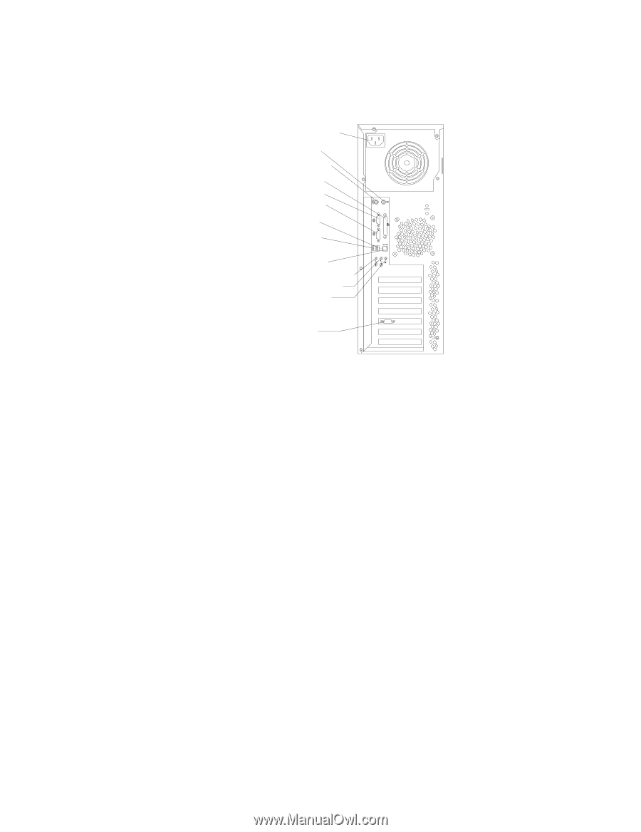
Server connectors The following illustration shows the connectors on the rear of the server. Rear View: Power cord Mouse Keyboard Parallel Serial 1 Serial 2 USB 1 USB 2 1 2 2 1 Ethernet Line out (green) Line in (blue) Mic (pink) Video Power-cord connector: Connect the power cord to this connector. Mouse connector: Connect a mouse or other PS/2® device to this connector. Keyboard connector: Connect a PS/2 keyboard to this connector. Parallel connector: Connect a parallel device to this connector. Serial 1 connector: Connect a 9-pin serial device to this connector. Serial 2 connector: Connect a 9-pin serial device to this connector USB 1 connector: Connect a USB device to this connector. USB 2 connector: Connect a USB device to this connector. Ethernet connector: Use this connector to connect the server to a network. Mic connector (pink): Connect a microphone to this connector. Line out connector (green): Connect an audio output device, such as speakers, to this connector. Line in connector (blue): Connect an audio input device, such as a stereo, to this connector. Video connector: Connect a monitor to this connector. If you have an optional Remote Supervisor Adapter (system-management adapter) installed in PCI slot 1, your server has additional connectors and LEDs. See the Option Installation Guide for more information about these connectors and LEDs. Chapter 1. Introducing the xSeries 205 Type 8480 server 7
-
 1
1 -
2
-
3
-
4
-
5
-
6
-
7
-
8
-
9
-
10
-
11
-
12
-
13
-
 14
14 -
 15
15 -
 16
16 -
 17
17 -
 18
18 -
 19
19 -
 20
20 -
 21
21 -
 22
22 -
 23
23 -
 24
24 -
25
-
26
-
27
-
28
-
29
-
30
-
31
-
32
-
33
-
34
-
35
-
36
-
37
-
38
-
39
-
40
-
41
-
42
-
43
-
44
-
45
-
46
-
47
-
48
-
49
-
50
-
51
-
52
-
53
-
54
-
55
-
56
-
57
-
58
-
59
-
60
-
61
-
62
-
63
-
64
 |
 |