| Section |
Page |
| IBM xSeries 205 Type 8480 |
3 |
| IBM xSeries 205 Type 8480 |
3 |
| Installation Guide |
3 |
| SC25-P159-40 |
3 |
| Note |
4 |
| Note |
4 |
| Note |
4 |
| Note |
4 |
| Before using this information and the product it supports, be sure to read the general informatio... |
4 |
| First Edition (August 2002) |
4 |
| First Edition (August 2002) |
4 |
| © Copyright International Business Machines Corporation 2002. All rights reserved. |
4 |
| © Copyright International Business Machines Corporation 2002. All rights reserved. |
4 |
| US Government Users Restricted Rights – Use, duplication or disclosure restricted by GSA ADP Sche... |
4 |
| Safety |
7 |
| Safety |
7 |
| <GRAPHIC> |
7 |
| <GRAPHIC> |
7 |
| Antes de instalar este produto, leia as Informações de Segurança. |
7 |
| <GRAPHIC> |
7 |
| <GRAPHIC> |
7 |
| <GRAPHIC> |
7 |
| <GRAPHIC> |
7 |
| <GRAPHIC> |
7 |
| <GRAPHIC> |
7 |
| <GRAPHIC> |
7 |
| <GRAPHIC> |
7 |
| Læs sikkerhedsforskrifterne, før du installerer dette produkt. |
7 |
| Lees voordat u dit product installeert eerst de veiligheidsvoorschriften. |
7 |
| Ennen kuin asennat tämän tuotteen, lue turvaohjeet kohdasta Safety Information. |
7 |
| Avant d'installer ce produit, lisez les consignes de sécurité. |
7 |
| Vor der Installation dieses Produkts die Sicherheitshinweise lesen. |
7 |
| <GRAPHIC> |
7 |
| <GRAPHIC> |
7 |
| <GRAPHIC> |
7 |
| <GRAPHIC> |
7 |
| <GRAPHIC> |
7 |
| <GRAPHIC> |
7 |
| Prima di installare questo prodotto, leggere le Informazioni sulla Sicurezza |
7 |
| <GRAPHIC> |
7 |
| <GRAPHIC> |
7 |
| <GRAPHIC> |
7 |
| <GRAPHIC> |
7 |
| <GRAPHIC> |
7 |
| <GRAPHIC> |
7 |
| Les sikkerhetsinformasjonen (Safety Information) før du installerer dette produktet. |
7 |
| <GRAPHIC> |
7 |
| <GRAPHIC> |
7 |
| Antes de instalar este produto, leia as Informações sobre Segurança. |
7 |
| <GRAPHIC> |
7 |
| <GRAPHIC> |
7 |
| <GRAPHIC> |
7 |
| <GRAPHIC> |
7 |
| <GRAPHIC> |
8 |
| <GRAPHIC> |
8 |
| Antes de instalar este producto lea la información de seguridad. |
8 |
| Läs säkerhetsinformationen innan du installerar den här produkten. |
8 |
| Statement 1 |
8 |
| Statement 1 |
8 |
| <GRAPHIC> |
8 |
| <GRAPHIC> |
8 |
| <GRAPHIC> |
8 |
| <GRAPHIC> |
8 |
| <TABLE> |
8 |
| <TABLE HEADING> |
8 |
| <TABLE ROW> |
8 |
| To Connect: |
8 |
| To Disconnect: |
8 |
| <TABLE BODY> |
8 |
| <TABLE ROW> |
8 |
| 1. Turn everything OFF. |
8 |
| 1. Turn everything OFF. |
8 |
| 1. Turn everything OFF. |
8 |
| 2. First, attach all cables to devices. |
8 |
| 3. Attach signal cables to connectors. |
8 |
| 4. Attach power cords to outlet. |
8 |
| 5. Turn device ON. |
8 |
| 1. Turn everything OFF. |
8 |
| 1. Turn everything OFF. |
8 |
| 1. Turn everything OFF. |
8 |
| 2. First, remove power cords from outlet. |
8 |
| 3. Remove signal cables from connectors. |
8 |
| 4. Remove all cables from devices. |
8 |
| Statement 2 |
9 |
| Statement 2 |
9 |
| <GRAPHIC> |
9 |
| <GRAPHIC> |
9 |
| When replacing the lithium battery, use only |
9 |
| Statement 3 |
9 |
| Statement 3 |
9 |
| <GRAPHIC> |
9 |
| <GRAPHIC> |
9 |
| When laser products (such as CD-ROMs, DVD drives, fiber optic devices, or transmitters) are insta... |
9 |
| <GRAPHIC> |
9 |
| <GRAPHIC> |
9 |
| <GRAPHIC> |
9 |
| <GRAPHIC> |
9 |
| <GRAPHIC> |
9 |
| Statement 4 |
10 |
| Statement 4 |
10 |
| <GRAPHIC> |
10 |
| <GRAPHIC> |
10 |
| <TABLE> |
10 |
| <TABLE> |
10 |
| <TABLE BODY> |
10 |
| <TABLE ROW> |
10 |
| <GRAPHIC> |
10 |
| <GRAPHIC> |
10 |
| <GRAPHIC> |
10 |
| <GRAPHIC> |
10 |
| <GRAPHIC> |
10 |
| <GRAPHIC> |
10 |
| <TABLE ROW> |
10 |
| ³ 18 kg (39.7 lb) |
10 |
| ³ 32 kg (70.5 lb) |
10 |
| ³ 55 kg (121.2 lb) |
10 |
| Use safe practices when lifting. |
10 |
| Statement 5 |
10 |
| Statement 5 |
10 |
| <GRAPHIC> |
10 |
| <GRAPHIC> |
10 |
| The power control button on the device and the power switch on the power supply do not turn off t... |
10 |
| <GRAPHIC> |
10 |
| <GRAPHIC> |
10 |
| Statement 8 |
11 |
| Statement 8 |
11 |
| <GRAPHIC> |
11 |
| <GRAPHIC> |
11 |
| Never remove the cover on a power supply or any part that has the following label attached. |
11 |
| Chapter 1.� Introduction |
13 |
| Chapter 1.� Introduction |
13 |
| Chapter 1.� Introduction |
13 |
| Chapter 1.� Introduction |
13 |
| Thank you for purchasing an |
13 |
| Thank you for purchasing an |
13 |
| Packaged with this Installation Guide are software CDs that you can use to configure the hardware... |
13 |
| Also included is an |
13 |
| If you have access to the World Wide Web, you can obtain up-to-date information about your server... |
13 |
| Record information about your server in the following table. |
13 |
| <TABLE> |
13 |
| <TABLE> |
13 |
| <TABLE BODY> |
13 |
| <TABLE ROW> |
13 |
| <TABLE ROW> |
13 |
| Product name |
13 |
| Product name |
13 |
| IBM Eserver xSeries 205 server |
13 |
| IBM |
13 |
| <TABLE ROW> |
13 |
| Machine type |
13 |
| Machine type |
13 |
| 8480 |
13 |
| <TABLE ROW> |
13 |
| Model number |
13 |
| Model number |
13 |
| _____________________________________________ |
13 |
| <TABLE ROW> |
13 |
| Serial number |
13 |
| Serial number |
13 |
| _____________________________________________ |
13 |
| <TABLE ROW> |
13 |
| Key serial number |
13 |
| Key serial number |
13 |
| _____________________________________________ |
13 |
| <TABLE ROW> |
13 |
| Key manufacturer |
13 |
| Key manufacturer |
13 |
| _____________________________________________ |
13 |
| <TABLE ROW> |
13 |
| Key phone number |
13 |
| Key phone number |
13 |
| _____________________________________________ |
13 |
| The server model and serial numbers are on labels on the lower-right side of the bezel. |
13 |
| Important |
13 |
| Important |
13 |
| Your server keys cannot be duplicated by a locksmith. If you lose them, order replacement keys fr... |
13 |
| If you plan to install your server in a rack, you need to purchase a |
13 |
| Features and specifications |
14 |
| Features and specifications |
14 |
| Features and specifications |
14 |
| Features and specifications |
14 |
| The following table provides a summary of the features and specifications of your |
14 |
| The following table provides a summary of the features and specifications of your |
14 |
| <TABLE> |
14 |
| <TABLE> |
14 |
| Table 1. Features and Specifications� |
14 |
| Table 1. Features and Specifications |
14 |
| <TABLE BODY> |
14 |
| <TABLE ROW> |
14 |
| Microprocessor: Supports one microprocessor — Intel® Pentium® 4 with 128 KB, 256 KB, or 512 KB Le... |
14 |
| Microprocessor: |
14 |
| Microprocessor: |
14 |
| Memory: |
14 |
| • Minimum: 128 MB |
14 |
| • Minimum: 128 MB |
14 |
| • Maximum: 2.0 GB |
14 |
| • Type: PC2100 266 MHz double- density RAM (DDR) DIMMs |
14 |
| • Slots: Two dual inline |
14 |
| Drives: |
14 |
| Size: |
14 |
| Size: |
14 |
| • Height: 470 mm (18.5 in.) |
14 |
| • Height: 470 mm (18.5 in.) |
14 |
| • Depth: 508 mm (19.9 in.) |
14 |
| • Width: 165 mm (6.5 in.) |
14 |
| • Weight: approximately 19.5 kg (43 lb) when fully configured or 15.9 kg (35 lb) minimum |
14 |
| Integrated functions: |
14 |
| • Broadcom 5702 10/100/1000 Ethernet controller on the system board with RJ-45 Ethernet connector |
14 |
| • Broadcom 5702 10/100/1000 Ethernet controller on the system board with RJ-45 Ethernet connector |
14 |
| • Two serial ports |
14 |
| • Parallel port |
14 |
| • Two USB ports |
14 |
| • Keyboard port |
14 |
| • Mouse port |
14 |
| • Audio ports |
14 |
| • Dual-channel bus mastering IDE controller |
14 |
| • Support for |
14 |
| Acoustical noise emissions |
14 |
| • Sound power, idling: 5.1 bel maximum |
14 |
| • Sound power, idling: 5.1 bel maximum |
14 |
| • Sound power, operating: 5.3 bel maximum |
14 |
| Environment: |
14 |
| Heat output: Approximate heat output in British thermal units (Btu) per hour: |
14 |
| Heat output |
14 |
| Notices and statements used in this book |
15 |
| Notices and statements used in this book |
15 |
| Notices and statements used in this book |
15 |
| Notices and statements used in this book |
15 |
| notices:book |
15 |
| notices:book |
15 |
| notices:book |
15 |
| notices:important |
15 |
| notices:attention |
15 |
| notices:caution |
15 |
| notices:danger |
15 |
| statements:danger |
15 |
| statements:attention |
15 |
| statements:caution |
15 |
| statements:important |
15 |
| The following notices and statements are used in the documentation: |
15 |
| • Notes: |
15 |
| • Notes: |
15 |
| • Notes: |
15 |
| • Notes: |
15 |
| • Important: |
15 |
| • Important: |
15 |
| • Attention: |
15 |
| • Attention: |
15 |
| • Caution: |
15 |
| • Caution: |
15 |
| • Danger: |
15 |
| • Danger: |
15 |
| Major components of the |
15 |
| Major components of the |
15 |
| Major components of the |
15 |
| Major components of the |
15 |
| The following illustration shows the locations of major |
15 |
| The following illustration shows the locations of major |
15 |
| System-board internal cable connectors |
16 |
| System-board internal cable connectors |
16 |
| System-board internal cable connectors |
16 |
| System-board internal cable connectors |
16 |
| The following illustration identifies system and extender board connectors for internal cables. |
16 |
| The following illustration identifies system and extender board connectors for internal cables. |
16 |
| Chapter 2.� Installing options |
17 |
| Chapter 2.� Installing options |
17 |
| Chapter 2.� Installing options |
17 |
| Chapter 2.� Installing options |
17 |
| installing:options |
17 |
| installing:options |
17 |
| installing:options |
17 |
| Installation guidelines |
17 |
| Installation guidelines |
17 |
| Installation guidelines |
17 |
| Installation guidelines |
17 |
| guidelines:installation |
17 |
| guidelines:installation |
17 |
| guidelines:installation |
17 |
| System reliability guidelines |
17 |
| System reliability guidelines |
17 |
| System reliability guidelines |
17 |
| System reliability guidelines |
17 |
| guidelines:system reliability |
17 |
| guidelines:system reliability |
17 |
| guidelines:system reliability |
17 |
| Working inside the server with the power on |
17 |
| Working inside the server with the power on |
17 |
| Working inside the server with the power on |
17 |
| Working inside the server with the power on |
17 |
| Your server supports hot-plug, hot-add, and hot-swap devices and is designed to operate safely wh... |
17 |
| Your server supports hot-plug, hot-add, and hot-swap devices and is designed to operate safely wh... |
17 |
| Handling static-sensitive devices |
18 |
| Handling static-sensitive devices |
18 |
| Handling static-sensitive devices |
18 |
| Handling static-sensitive devices |
18 |
| Static electricity can damage electronic devices, including your server. To avoid damage, keep st... |
18 |
| Static electricity can damage electronic devices, including your server. To avoid damage, keep st... |
18 |
| devices:handling static-sensitive |
18 |
| devices:handling static-sensitive |
18 |
| handling static-sensitive devices |
18 |
| Moving the stabilizing feet |
18 |
| Moving the stabilizing feet |
18 |
| Moving the stabilizing feet |
18 |
| Moving the stabilizing feet |
18 |
| stabilizing feet |
18 |
| stabilizing feet |
18 |
| stabilizing feet |
18 |
| Complete the following steps to place the feet in the stabilizing position: |
18 |
| 1. Place the server on its side. |
18 |
| 1. Place the server on its side. |
18 |
| 1. Place the server on its side. |
18 |
| 2. Locate the release tab inside the foot; then, lift up on the tab. |
18 |
| 3. Rotate the foot inward to the unlocked position; then, remove the foot from the server. |
18 |
| 4. Align the post in the center of the foot with the hole on the bottom of the server and place t... |
19 |
| 5. Rotate the foot outward until the foot locks into place. |
19 |
| 6. Complete steps |
19 |
| Removing the side cover |
20 |
| Removing the side cover |
20 |
| Removing the side cover |
20 |
| Removing the side cover |
20 |
| removing:side cover |
20 |
| removing:side cover |
20 |
| removing:side cover |
20 |
| cover:removing |
20 |
| To replace the side cover, see |
20 |
| For proper cooling and airflow, replace the side cover before turning on the server. Operating th... |
20 |
| Removing the frame-support bracket |
21 |
| Removing the frame-support bracket |
21 |
| Removing the frame-support bracket |
21 |
| Removing the frame-support bracket |
21 |
| When working with some options such as hard disk drives, microprocessors, and memory modules, you... |
21 |
| When working with some options such as hard disk drives, microprocessors, and memory modules, you... |
21 |
| Complete the following steps to remove the frame-support bracket: |
21 |
| To reinstall the frame-support bracket, reverse these steps. |
21 |
| Working with adapters |
22 |
| Working with adapters |
22 |
| Working with adapters |
22 |
| Working with adapters |
22 |
| Your server comes with five PCI adapter connectors, or |
22 |
| Your server comes with five PCI adapter connectors, or |
22 |
| The following illustration shows the location of the PCI |
22 |
| Adapter considerations |
22 |
| Adapter considerations |
22 |
| Adapter considerations |
22 |
| Adapter considerations |
22 |
| Before you install an adapter, review the following information: |
22 |
| Before you install an adapter, review the following information: |
22 |
| • Locate the documentation that comes with the adapter and follow those instructions in addition ... |
22 |
| • Locate the documentation that comes with the adapter and follow those instructions in addition ... |
22 |
| • Locate the documentation that comes with the adapter and follow those instructions in addition ... |
22 |
| • You can install |
22 |
| • Your server supports 5.0�V and universal PCI adapters; it does not support 3.3�V adapters. |
22 |
| • Your server uses a rotational interrupt technique to configure PCI adapters. Therefore, you can... |
22 |
| • If you are installing an adapter that will control your startup (boot) drive, install the adapt... |
23 |
| adapter:PCI bus |
23 |
| adapter:PCI bus |
23 |
| • For a list of supported options for your server, go to http://www.ibm.com/pc/compat/ on the Wor... |
23 |
| Installing an adapter |
23 |
| Installing an adapter |
23 |
| Installing an adapter |
23 |
| Installing an adapter |
23 |
| Complete the following steps to install an adapter. |
23 |
| Complete the following steps to install an adapter. |
23 |
| When you handle static-sensitive devices, take precautions to avoid damage from static electricit... |
23 |
| 1. Review the safety precautions listed in |
23 |
| 1. Review the safety precautions listed in |
23 |
| 2. Turn off the server and peripheral devices and disconnect all external cables and power cords;... |
23 |
| 3. Remove the frame-support bracket. See |
23 |
| 4. If you are installing a full-length adapter, rotate the front adapter-support bracket to the o... |
23 |
| 5. Rotate the rear adapter-retaining bracket to the open (unlocked) position, and then remove it ... |
23 |
| 6. Remove the PCI expansion-slot cover. From the rear of the server, press in on the slot cover. ... |
23 |
| 7. Touch the static-protective package containing the adapter to any unpainted metal surface on t... |
23 |
| 8. Place the adapter on a flat, static-protective surface, and set any jumpers or switches as des... |
23 |
| 9. Carefully grasp the adapter by its top edge or upper corners, and align it with the expansion ... |
24 |
| 10. Connect required cables to the adapter. |
24 |
| 11. If you have another adapter to install, do so now. |
24 |
| 12. If you have installed a full-length adapter, rotate the front adapter-support bracket to the ... |
24 |
| 13. Reinstall the rear adapter-retaining bracket; then, rotate the bracket to the closed (locked)... |
24 |
| 14. If you have other options to install, do so now. |
24 |
| 15. Reinstall the side cover (see |
24 |
| 16. Reconnect the external cables and power cords; then, turn on the peripheral devices and the s... |
24 |
| Installing a SCSI or RAID adapter |
25 |
| Installing a SCSI or RAID adapter |
25 |
| Installing a SCSI or RAID adapter |
25 |
| Installing a SCSI or RAID adapter |
25 |
| small computer systems interface (SCSI):adapter |
25 |
| small computer systems interface (SCSI):adapter |
25 |
| small computer systems interface (SCSI):adapter |
25 |
| installing:small computer systems interface (SCSI) adapter |
25 |
| installing:redundant arrays of independent drives (RAID) adapter |
25 |
| installing:drive |
25 |
| Installing internal drives |
26 |
| Installing internal drives |
26 |
| Installing internal drives |
26 |
| Installing internal drives |
26 |
| Your server comes with an IDE CD-ROM drive installed in bay 1 and a 3.5-in., 1.44 MB diskette dri... |
26 |
| Your server comes with an IDE CD-ROM drive installed in bay 1 and a 3.5-in., 1.44 MB diskette dri... |
26 |
| Before you install an internal drive, review the following information: |
26 |
| • Diskette drives, tape drives, and CD-ROM drives are removable-media drives. You can install rem... |
26 |
| • Diskette drives, tape drives, and CD-ROM drives are removable-media drives. You can install rem... |
26 |
| • You can install a 3.5-in., slim-high or a 5.25-in., half-high, removable-media drive, such as a... |
26 |
| • You can install only a 3.5-in., slim-high, removable-media drive in bay 4. |
26 |
| • The |
26 |
| • Before you install a 3.5-in. drive in a 5.25-in. bay, you must attach the 5.25-in. conversion k... |
26 |
| • If you have a tape backup drive in your server, use a dry-process cleaning cartridge to clean t... |
26 |
| • The electromagnetic interference (EMI) integrity and cooling of the server are both protected b... |
26 |
| • For a list of supported options for your server, go to http://www.ibm.com/pc/compat/ on the Wor... |
27 |
| Preinstallation steps (all bays) |
27 |
| Preinstallation steps (all bays) |
27 |
| Preinstallation steps (all bays) |
27 |
| Preinstallation steps (all bays) |
27 |
| Before you install drives in your server, verify that you have all the cables and any other equip... |
27 |
| Before you install drives in your server, verify that you have all the cables and any other equip... |
27 |
| Power and signal cables for internal drives |
27 |
| Power and signal cables for internal drives |
27 |
| Power and signal cables for internal drives |
27 |
| Power and signal cables for internal drives |
27 |
| cables:internal drives |
27 |
| cables:internal drives |
27 |
| cables:internal drives |
27 |
| cables:power |
27 |
| cables:signal |
27 |
| To locate connectors on the system board, see |
27 |
| Review the following information before connecting power and signal cables to internal drives: |
28 |
| bay: 2 or 4 |
28 |
| bay: 2 or 4 |
28 |
| bay: 2 or 4 |
28 |
| bay: 2 or 4 |
28 |
| bay: 2 or 4 |
28 |
| Complete the following steps to install a drive in bay 2 or 4. |
28 |
| Complete the following steps to install a drive in bay 2 or 4. |
28 |
| When you handle static-sensitive devices, take precautions to avoid damage from static electricit... |
28 |
| 1. Review the safety precautions listed in |
28 |
| 1. Review the safety precautions listed in |
28 |
| 2. Turn off the server and peripheral devices and disconnect the external cables and power cords;... |
28 |
| 3. Remove the frame-support bracket and disconnect the fan cable from the connector on the system... |
28 |
| 4. Use a screwdriver to gently pry the |
28 |
| 5. Touch the static-protective package containing the drive to any unpainted metal surface on the... |
29 |
| 6. Set any jumpers or switches on the drive according to the documentation that comes with the dr... |
29 |
| 7. Install the drive: |
30 |
| drive:cabling |
30 |
| drive:cabling |
30 |
| 9. If you have another drive to install or remove, do so now. |
30 |
| 10. Plug one of the power cables from the power supply into the back of the drive. The connectors... |
30 |
| 11. Replace the frame-support bracket. |
30 |
| 12. If you have other options to install, do so now. |
30 |
| 13. Reinstall the side cover. See |
30 |
| 14. Reconnect the external cables and power cords; then, turn on the peripheral devices and the s... |
31 |
| bay:5, 6, or 7 |
31 |
| bay:5, 6, or 7 |
31 |
| bay:5, 6, or 7 |
31 |
| bay:5, 6, or 7 |
31 |
| bay:5, 6, or 7 |
31 |
| Complete the following steps to install a hard disk drive in bay 5, 6, or 7. |
31 |
| Complete the following steps to install a hard disk drive in bay 5, 6, or 7. |
31 |
| When you handle static-sensitive devices, take precautions to avoid damage from static electricit... |
31 |
| 1. Review the safety precautions listed in |
31 |
| 1. Review the safety precautions listed in |
31 |
| 2. Read the information in |
31 |
| 3. Turn off the server and peripheral devices and disconnect all external cables and power cords;... |
31 |
| 4. Remove the frame-support bracket. See |
31 |
| 5. Access the drive cage: |
31 |
| 6. Touch the static-protective package containing the drive to any unpainted metal surface on the... |
31 |
| 7. Set any jumpers or switches on the drive according to the documentation that comes with the dr... |
31 |
| 8. Attach the blue plastic guide rails to the sides of the drive using the screws and guide rails... |
31 |
| 9. Slide the drive into the drive cage until the plastic tabs on the guide rails lock into place ... |
31 |
| 10. Press in on the drive-cage-retention tab, and rotate the drive cage back into the server. |
32 |
| 11. Connect the power and signal cables to the rear of each drive. |
32 |
| 12. If you have other options to install or remove, do so now. |
32 |
| 13. Replace the frame-support bracket. See |
32 |
| 14. Reinstall the side cover. See |
32 |
| 15. Reconnect the external cables and power cords; then, turn on the peripheral devices and the s... |
32 |
| Installing a hot-swap hard disk drive in bay 5, 6, or 7 |
32 |
| Installing a hot-swap hard disk drive in bay 5, 6, or 7 |
32 |
| Installing a hot-swap hard disk drive in bay 5, 6, or 7 |
32 |
| Installing a hot-swap hard disk drive in bay 5, 6, or 7 |
32 |
| bay:open |
32 |
| bay:open |
32 |
| bay:open |
32 |
| installing:hot-swap hard disk drive |
32 |
| installing:hard disk drive |
32 |
| Each hot-swap drive has two LEDs: the hard disk drive activity LED and the hard disk drive status... |
32 |
| Each hot-swap drive that you plan to install comes mounted in a hot-swap-drive tray. The drive mu... |
33 |
| The hot-swap bays are connected to a |
33 |
| The following illustration shows the hot-swap-drive backplane component locations, as viewed from... |
33 |
| The following illustration shows the rear connectors on the hot-swap-drive backplane, as viewed f... |
33 |
| When you install hot-swap hard disk drives, install them in the following order: bay 7, bay 6, an... |
33 |
| When you install hot-swap hard disk drives, install them in the following order: bay 7, bay 6, an... |
33 |
| • When you handle static-sensitive devices, take precautions to avoid damage from static electric... |
34 |
| • When you handle static-sensitive devices, take precautions to avoid damage from static electric... |
34 |
| • When you handle static-sensitive devices, take precautions to avoid damage from static electric... |
34 |
| • To maintain proper system cooling, do not operate the server for more than 10 minutes without e... |
34 |
| Complete the following steps to install a hot-swap hard disk drive in bay 5, 6, or 7. |
34 |
| Installing memory modules |
35 |
| Installing memory modules |
35 |
| Installing memory modules |
35 |
| Installing memory modules |
35 |
| Your server comes with a dual inline memory module (DIMM) installed on the system board in DIMM c... |
35 |
| Your server comes with a dual inline memory module (DIMM) installed on the system board in DIMM c... |
35 |
| Before you install memory modules, review the following information: |
35 |
| DIMM:connector locations |
35 |
| DIMM:connector locations |
35 |
| DIMM:installing |
35 |
| When you handle static-sensitive devices, take precautions to avoid damage from static electricit... |
35 |
| 1. Review the safety precautions listed in |
35 |
| 1. Review the safety precautions listed in |
35 |
| 2. Turn off the server and peripheral devices and disconnect all external cables and power cords;... |
35 |
| 3. Remove the frame-support bracket. See |
35 |
| 4. Touch the static-protective package containing the DIMM to any unpainted metal surface on the ... |
35 |
| 5. Gently open the retaining clip on each end of the DIMM connector. Turn the DIMM so that the pi... |
35 |
| 6. Insert the DIMM into the connector. Firmly press the DIMM straight down into the connector by ... |
35 |
| 7. If there is a gap between the DIMM and the retaining clips, the DIMM has not been properly ins... |
36 |
| 8. If you have other options to install or remove, do so now. |
36 |
| 9. Replace the frame-support bracket. See |
36 |
| 10. Replace the side cover. See |
36 |
| 11. Reconnect the external cables and power cords; then, turn on the peripheral devices and the s... |
36 |
| If you want to remove a DIMM, reverse these steps. |
36 |
| Installing a security rope clip |
36 |
| Installing a security rope clip |
36 |
| Installing a security rope clip |
36 |
| Installing a security rope clip |
36 |
| installing:security rope clip |
36 |
| installing:security rope clip |
36 |
| installing:security rope clip |
36 |
| Before you begin: |
36 |
| Complete the following steps to install a rope clip: |
37 |
| Installing the side cover |
37 |
| Installing the side cover |
37 |
| Installing the side cover |
37 |
| Installing the side cover |
37 |
| installing:side cover |
37 |
| installing:side cover |
37 |
| If you removed the frame-support bracket after you removed the side cover, reinstall it before yo... |
37 |
| If you removed the frame-support bracket after you removed the side cover, reinstall it before yo... |
37 |
| Complete the following steps to install the side cover: |
38 |
| 1. Clear any cables that might impede the reinstallation of the side cover. |
38 |
| 1. Clear any cables that might impede the reinstallation of the side cover. |
38 |
| 2. Install the side cover. |
38 |
| 3. Lock the side cover. |
38 |
| 4. If you have not done so already, make sure the stabilizing feet are in the stabilizing positio... |
38 |
| 5. Reconnect the external cables and power cords to the server, and then plug the power cords int... |
38 |
| 6. Turn on the peripheral devices; then, turn on the server. |
38 |
| Cabling the server |
38 |
| Cabling the server |
38 |
| Cabling the server |
38 |
| Cabling the server |
38 |
| cabling:server |
38 |
| cabling:server |
38 |
| cabling:server |
38 |
| server:cabling |
38 |
| The following illustration shows the I/O connectors on the rear of the server. |
39 |
| Your server has one keyboard connector on the back of the server. Use this connector to attach a ... |
39 |
| You can also connect a USB keyboard to the server using one of the USB connectors. After installi... |
39 |
| Chapter 3.� Server controls, LEDs, and power |
41 |
| Chapter 3.� Server controls, LEDs, and power |
41 |
| Chapter 3.� Server controls, LEDs, and power |
41 |
| Chapter 3.� Server controls, LEDs, and power |
41 |
| This chapter describes the controls and light-emitting diodes (LEDs) and how to turn the server o... |
41 |
| This chapter describes the controls and light-emitting diodes (LEDs) and how to turn the server o... |
41 |
| Server controls and LEDs |
41 |
| Server controls and LEDs |
41 |
| Server controls and LEDs |
41 |
| Server controls and LEDs |
41 |
| <GRAPHIC> |
41 |
| <GRAPHIC> |
41 |
| <GRAPHIC> |
41 |
| Ethernet speed 1 Gbps LED |
41 |
| Ethernet speed 1 Gbps LED |
41 |
| Ethernet transmit/receive activity LED |
41 |
| Ethernet transmit/receive activity LED |
41 |
| CD-eject button: |
41 |
| CD-eject button: |
41 |
| CD-ROM drive activity |
41 |
| CD-ROM drive activity |
41 |
| Diskette-eject button: |
41 |
| Diskette-eject button: |
41 |
| Diskette drive activity LED |
41 |
| Diskette drive activity LED |
41 |
| Hard disk drive activity LED |
41 |
| Hard disk drive activity LED |
41 |
| Power-on LED |
41 |
| Power-on LED |
41 |
| Power-control button: |
41 |
| Power-control button: |
41 |
| Server power fe |
42 |
| Server power fe |
42 |
| Server power fe |
42 |
| Server power fe |
42 |
| When you connect the server to an ac power source, the server goes into Standby mode. After appro... |
42 |
| When you connect the server to an ac power source, the server goes into Standby mode. After appro... |
42 |
| A power-control-button shield comes with your server. You can install this disk-shaped shield to ... |
42 |
| Turning on the server |
42 |
| Turning on the server |
42 |
| Turning on the server |
42 |
| Turning on the server |
42 |
| server: turning on |
42 |
| server: turning on |
42 |
| server: turning on |
42 |
| turning on the server |
42 |
| Turning off the server |
42 |
| Turning off the server |
42 |
| Turning off the server |
42 |
| Turning off the server |
42 |
| server: turning off |
42 |
| server: turning off |
42 |
| server: turning off |
42 |
| turning off the server |
42 |
| <TABLE> |
42 |
| <TABLE> |
42 |
| <TABLE HEADING> |
42 |
| <TABLE ROW> |
42 |
| Statement 5 |
42 |
| <TABLE BODY> |
42 |
| <TABLE ROW> |
42 |
| <GRAPHIC> |
42 |
| <GRAPHIC> |
42 |
| <GRAPHIC> |
42 |
| <GRAPHIC> |
42 |
| <TABLE ROW> |
42 |
| CAUTION: The power control button on the device and the power switch on the power supply do not t... |
42 |
| The power control button on the device and the power switch on the power supply do not turn off t... |
42 |
| <TABLE ROW> |
42 |
| <TABLE ROW> |
42 |
| <GRAPHIC> |
42 |
| <GRAPHIC> |
42 |
| The server can be turned off in any of the following ways: |
43 |
| Standby mode |
43 |
| Standby mode |
43 |
| Standby mode |
43 |
| Standby mode |
43 |
| When the server is connected to an ac power source but has not been turned on, it is in Standby m... |
43 |
| When the server is connected to an ac power source but has not been turned on, it is in Standby m... |
43 |
| To put the server into Standby mode when the server is turned on, shut down the operating system ... |
43 |
| You can also put the server into Standby mode through a request from the service processor. |
43 |
| Chapter 4.� Configuring your server |
45 |
| Chapter 4.� Configuring your server |
45 |
| Chapter 4.� Configuring your server |
45 |
| Chapter 4.� Configuring your server |
45 |
| The following configuration programs are provided with your server. |
45 |
| The following configuration programs are provided with your server. |
45 |
| configuration programs |
45 |
| server: configuring |
45 |
| server:configuring |
45 |
| • Configuration/Setup Utility |
45 |
| • Configuration/Setup Utility |
45 |
| • Configuration/Setup Utility |
45 |
| • Configuration/Setup Utility |
45 |
| This program is part of the basic input/output system (BIOS) code that comes with your server. Yo... |
45 |
| • Broadcom NetXtreme Gigabit Ethernet Boot Agent |
45 |
| • Broadcom NetXtreme Gigabit Ethernet Boot Agent |
45 |
| The Broadcom NetXtreme Gigabit Ethernet Boot Agent is part of the BIOS code that comes with your ... |
45 |
| • SCSISelect Utility |
45 |
| • SCSISelect Utility |
45 |
| • ServerGui |
45 |
| • ServerGui |
45 |
| See the |
45 |
| Starting the Configuration/Setup Utility program |
45 |
| Starting the Configuration/Setup Utility program |
45 |
| Starting the Configuration/Setup Utility program |
45 |
| Starting the Configuration/Setup Utility program |
45 |
| Configuration/Setup Utility program |
45 |
| Configuration/Setup Utility program |
45 |
| Configuration/Setup Utility program |
45 |
| utility:Configuration/Setup |
45 |
| The Configuration/Setup Utility program is a menu-driven utility that is part of the BIOS code th... |
45 |
| Complete the following steps to start the Configuration/Setup Utility program: |
45 |
| Starting the Broadcom NetXtreme Gigabit Ethernet Boot Agent program |
46 |
| Starting the Broadcom NetXtreme Gigabit Ethernet Boot Agent program |
46 |
| Starting the Broadcom NetXtreme Gigabit Ethernet Boot Agent program |
46 |
| Starting the Broadcom NetXtreme Gigabit Ethernet Boot Agent program |
46 |
| The Broadcom NetXtreme Gigabit Ethernet Boot Agent is part of the BIOS code that comes with your ... |
46 |
| The Broadcom NetXtreme Gigabit Ethernet Boot Agent is part of the BIOS code that comes with your ... |
46 |
| Starting the SCSISelect Utility program |
46 |
| Starting the SCSISelect Utility program |
46 |
| Starting the SCSISelect Utility program |
46 |
| Starting the SCSISelect Utility program |
46 |
| SCSISelect Utility program |
46 |
| SCSISelect Utility program |
46 |
| utility:SCSISelect |
46 |
| SCSISelect is a menu-driven configuration utility program for models that come with a SCSI adapte... |
46 |
| • View the default SCSI IDs |
46 |
| • View the default SCSI IDs |
46 |
| • Locate and correct configuration conflicts |
46 |
| If your server has a redundant arrays of independent disks (RAID) adapter installed, use the conf... |
46 |
| If your server has a redundant arrays of independent disks (RAID) adapter installed, use the conf... |
46 |
| If your server has a redundant arrays of independent disks (RAID) adapter installed, use the conf... |
46 |
| Complete the following steps to start the SCSISelect Utility program: |
46 |
| Using the |
46 |
| Using the |
46 |
| Using the |
46 |
| Using the |
46 |
| The |
46 |
| The |
46 |
| If the |
46 |
| If the |
46 |
| 1. Insert the |
46 |
| 1. Insert the |
46 |
| 2. Follow the instructions that appear on the screen to: |
46 |
| Chapter 5.� Solving problems |
47 |
| Chapter 5.� Solving problems |
47 |
| Chapter 5.� Solving problems |
47 |
| Chapter 5.� Solving problems |
47 |
| This section provides basic |
47 |
| This section provides basic |
47 |
| If you cannot locate and correct the problem using the information in this section, see the |
47 |
| Diagnostic tools overview |
47 |
| Diagnostic tools overview |
47 |
| Diagnostic tools overview |
47 |
| Diagnostic tools overview |
47 |
| The following tools are available to help you identify and resolve hardware-related problems: |
47 |
| The following tools are available to help you identify and resolve hardware-related problems: |
47 |
| Power-on self-test (POST) |
47 |
| Power-on self-test (POST) |
47 |
| Power-on self-test (POST) |
47 |
| Power-on self-test (POST) |
47 |
| When you turn on the server, the Power On Self-Test (POST) performs a series of tests to check th... |
47 |
| When you turn on the server, the Power On Self-Test (POST) performs a series of tests to check th... |
47 |
| If POST finishes without detecting any problems, the first window of your operating system or app... |
47 |
| If POST detects a problem, more than one beep sounds and an error message appears on your screen. |
47 |
| Notes |
48 |
| Notes |
48 |
| 1. If you have a user password set, you must type the password and press Enter, when prompted, be... |
48 |
| 2. A single problem might cause several error messages. When this occurs, work to correct the cau... |
48 |
| POST beep codes |
48 |
| POST beep codes |
48 |
| POST beep codes |
48 |
| POST beep codes |
48 |
| beep codes |
48 |
| beep codes |
48 |
| beep codes |
48 |
| POST error messages |
48 |
| POST error messages |
48 |
| POST error messages |
48 |
| POST error messages |
48 |
| power-on self-test (POST):error messges |
48 |
| power-on self-test (POST):error messges |
48 |
| power-on self-test (POST):error messges |
48 |
| ServerGuide |
49 |
| ServerGuide |
49 |
| ServerGuide |
49 |
| ServerGuide |
49 |
| ServerGuide |
49 |
| Look for the symptom in the left column of the chart. Probable solutions to the problem are in th... |
49 |
| Look for the symptom in the left column of the chart. Probable solutions to the problem are in th... |
49 |
| Setup and Installation CD |
49 |
| Setup and Installation CD |
49 |
| <TABLE> |
49 |
| <TABLE> |
49 |
| <TABLE HEADING> |
49 |
| <TABLE ROW> |
49 |
| Symptom |
49 |
| Suggested action |
49 |
| <TABLE BODY> |
49 |
| <TABLE ROW> |
49 |
| Setup and Installation CD will not start. |
49 |
| Setup and Installation CD |
49 |
| Setup and Installation CD |
49 |
| Setup and Installation CD |
49 |
| Setup and Installation CD |
49 |
| Setup and Installation CD |
49 |
| • Ensure that the system is a supported server with a startable (bootable) CD-ROM drive. |
49 |
| • Ensure that the system is a supported server with a startable (bootable) CD-ROM drive. |
49 |
| • Ensure that the system is a supported server with a startable (bootable) CD-ROM drive. |
49 |
| • If the startup (boot) sequence settings have been altered, ensure that the CD-ROM drive is firs... |
49 |
| • If more than one CD-ROM drive is installed, ensure that only one drive is set as the primary dr... |
49 |
| <TABLE ROW> |
49 |
| ServeRAID™ program cannot view all installed drives or cannot install NOS. |
49 |
| ServeRAID |
49 |
| • Ensure that there are no duplicate SCSI IDs or IRQ assignments. |
49 |
| • Ensure that there are no duplicate SCSI IDs or IRQ assignments. |
49 |
| • Ensure that there are no duplicate SCSI IDs or IRQ assignments. |
49 |
| • Ensure that the hard disk drive is connected properly. |
49 |
| <TABLE ROW> |
49 |
| The Operating System Installation program continuously loops. |
49 |
| Make more space available on the hard disk. |
49 |
| <TABLE ROW> |
49 |
| ServerGuide will not start your NOS CD. |
49 |
| ServerGuide |
49 |
| Ensure that the NOS CD you have is supported by the ServerGuide program. See the Setup and Instal... |
49 |
| <TABLE ROW> |
49 |
| Cannot install NOS — option is unavailable. |
49 |
| Ensure that the NOS is supported on your server. If the NOS is supported, either there is no logi... |
49 |
| Troubleshooting chart |
50 |
| Troubleshooting chart |
50 |
| Troubleshooting chart |
50 |
| Troubleshooting chart |
50 |
| Notes |
50 |
| Notes |
50 |
| Notes |
50 |
| 1. See the |
50 |
| 2. If you cannot find the problem in the troubleshooting chart, run the diagnostic programs. If y... |
50 |
| <TABLE> |
50 |
| <TABLE> |
50 |
| <TABLE BODY> |
50 |
| <TABLE ROW> |
50 |
| Monitor |
50 |
| Monitor |
50 |
| Suggested Action |
50 |
| Suggested Action |
50 |
| <TABLE ROW> |
50 |
| The screen is blank. |
50 |
| Verify that: |
50 |
| <TABLE ROW> |
50 |
| Only the cursor appears. |
50 |
| Call for service. |
50 |
| <TABLE ROW> |
50 |
| The monitor works when you turn on the server, but goes blank when you start some application pro... |
50 |
| Verify that: |
50 |
| <TABLE ROW> |
50 |
| Wavy, unreadable, rolling, distorted screen, or screen jitter. |
50 |
| If the monitor self-tests show the monitor is OK, consider the location of the monitor. Magnetic ... |
50 |
| <TABLE ROW> |
50 |
| Wrong characters appear on the screen. |
50 |
| If the wrong language is displayed, update the BIOS code with the correct language. |
50 |
| <TABLE ROW> |
50 |
| Power |
50 |
| Power |
50 |
| Suggested action |
50 |
| Suggested action |
50 |
| <TABLE ROW> |
50 |
| The server does not turn on. |
50 |
| Verify that: |
50 |
| <TABLE ROW> |
51 |
| Memory |
51 |
| Memory |
51 |
| Suggested action |
51 |
| Suggested action |
51 |
| <TABLE ROW> |
51 |
| The amount of memory displayed is less than the amount of memory installed. |
51 |
| Verify that: |
51 |
| Verify that: |
51 |
| 1. The memory modules are seated properly. |
51 |
| 1. The memory modules are seated properly. |
51 |
| 2. You have installed the correct type of memory. |
51 |
| 3. If you changed the memory, you must update the memory configuration with the Configuration/Set... |
51 |
| 4. All banks of memory on the DIMMs are enabled. The server might have automatically disabled a D... |
51 |
| If the problem persists, call for service. |
51 |
| <TABLE ROW> |
51 |
| Option |
51 |
| Option |
51 |
| Suggested action |
51 |
| Suggested action |
51 |
| <TABLE ROW> |
51 |
| An IBM option that was just installed does not work. |
51 |
| Verify that: |
51 |
| <TABLE ROW> |
51 |
| Expansion enclosure |
51 |
| Expansion enclosure |
51 |
| Suggested action |
51 |
| Suggested action |
51 |
| <TABLE ROW> |
51 |
| The SCSI expansion enclosure used to work, but does not work now. |
51 |
| Verify that: |
51 |
| Verify that: |
51 |
| For more information, see your SCSI and expansion enclosure documentation. |
51 |
| Appendix A.� Getting help and technical assistance |
53 |
| Appendix A.� Getting help and technical assistance |
53 |
| Appendix A.� Getting help and technical assistance |
53 |
| Appendix A.� Getting help and technical assistance |
53 |
| If you need help, service, or technical assistance or just want more information about |
53 |
| If you need help, service, or technical assistance or just want more information about |
53 |
| Before you call |
53 |
| Before you call |
53 |
| Before you call |
53 |
| Before you call |
53 |
| Before you call, make sure that you have taken these steps to try to solve the problem yourself: |
53 |
| Before you call, make sure that you have taken these steps to try to solve the problem yourself: |
53 |
| You can solve many problems without outside assistance by following the troubleshooting procedure... |
53 |
| Using the documentation |
53 |
| Using the documentation |
53 |
| Using the documentation |
53 |
| Using the documentation |
53 |
| Information about your |
53 |
| Information about your |
53 |
| Getting help and information from the World Wide Web |
53 |
| Getting help and information from the World Wide Web |
53 |
| Getting help and information from the World Wide Web |
53 |
| Getting help and information from the World Wide Web |
53 |
| On the World Wide Web, the |
53 |
| On the World Wide Web, the |
53 |
| You can find service information for your |
53 |
| Software service and support |
54 |
| Software service and support |
54 |
| Software service and support |
54 |
| Software service and support |
54 |
| Through |
54 |
| Through |
54 |
| For more information about Support Line and other |
54 |
| Hardware service and support |
54 |
| Hardware service and support |
54 |
| Hardware service and support |
54 |
| Hardware service and support |
54 |
| You can receive hardware service through |
54 |
| You can receive hardware service through |
54 |
| In the U.S. and Canada, hardware service and support is available 24 hours a day, 7 days a week. ... |
54 |
| Appendix B.� Warranty information |
55 |
| Appendix B.� Warranty information |
55 |
| Appendix B.� Warranty information |
55 |
| Appendix B.� Warranty information |
55 |
| This section contains information about your warranty period and the service and support that are... |
55 |
| This section contains information about your warranty period and the service and support that are... |
55 |
| Warranty period |
55 |
| Warranty period |
55 |
| Warranty period |
55 |
| Warranty period |
55 |
| The warranty period varies by machine type and country or region. |
55 |
| The warranty period varies by machine type and country or region. |
55 |
| Contact your place of purchase for warranty service information. Some |
55 |
| Prior to on-site warranty service, you are required to go through problem determination with an |
55 |
| Prior to on-site warranty service, you are required to go through problem determination with an |
55 |
| A warranty period of 3 years on parts and 1 year on labor means that |
55 |
| The |
55 |
| Machine - |
55 |
| Machine - |
55 |
| IBM |
55 |
| <TABLE> |
55 |
| <TABLE> |
55 |
| <TABLE BODY> |
55 |
| <TABLE ROW> |
55 |
| Country or region |
55 |
| Country or region |
55 |
| Warranty period |
55 |
| Warranty period |
55 |
| Service delivery method |
55 |
| Service delivery method |
55 |
| <TABLE ROW> |
55 |
| Worldwide |
55 |
| 1 year |
55 |
| On-site |
55 |
| Problem determination |
55 |
| Problem determination |
55 |
| Problem determination |
55 |
| Problem determination |
55 |
| Prior to on-site warranty service, you are required to go through problem determination with an |
55 |
| Prior to on-site warranty service, you are required to go through problem determination with an |
55 |
| Running diagnostics |
55 |
| Running diagnostics |
55 |
| Running diagnostics |
55 |
| Running diagnostics |
55 |
| The |
55 |
| The |
55 |
| Checking software |
55 |
| Checking software |
55 |
| Checking software |
55 |
| Checking software |
55 |
| The |
55 |
| The |
55 |
| Warranty service and support |
56 |
| Warranty service and support |
56 |
| Warranty service and support |
56 |
| Warranty service and support |
56 |
| With the original purchase of an |
56 |
| With the original purchase of an |
56 |
| The following services are available during the warranty period: |
56 |
| The following items are not covered under warranty service: |
56 |
| See the |
56 |
| Please have the following information ready when you call: |
56 |
| International Warranty Service |
56 |
| International Warranty Service |
56 |
| International Warranty Service |
56 |
| International Warranty Service |
56 |
| If you travel with your |
56 |
| If you travel with your |
56 |
| You can obtain IWS through the service delivery method (such as depot, carry-in, or on-site) prov... |
56 |
| To determine whether your system is eligible for IWS, go to http://www.ibm.com/pc/support/ and click |
57 |
| Purchasing additional services |
57 |
| Purchasing additional services |
57 |
| Purchasing additional services |
57 |
| Purchasing additional services |
57 |
| During and after the warranty period, you can purchase additional services, such as support for |
57 |
| During and after the warranty period, you can purchase additional services, such as support for |
57 |
| For more information about these services, contact your |
57 |
| IBM |
58 |
| IBM |
58 |
| IBM |
58 |
| IBM |
58 |
| IBM |
58 |
| Part 1 - General Terms |
58 |
| Part 1 - General Terms |
58 |
| Part 1 - General Terms |
58 |
| Part 1 - General Terms |
58 |
| Part 1 - General Terms |
58 |
| This Statement of Limited Warranty includes Part 1 - General Terms and Part 2 - Country-unique Te... |
58 |
| This Statement of Limited Warranty includes Part 1 - General Terms and Part 2 - Country-unique Te... |
58 |
| The |
58 |
| The |
58 |
| If a Machine does not function as warranted during the warranty period, and |
58 |
| Extent of Warranty: |
58 |
| Extent of Warranty: |
58 |
| THESE WARRANTIES ARE YOUR EXCLUSIVE WARRANTIES AND REPLACE ALL OTHER WARRANTIES OR CONDITIONS, EX... |
58 |
| THESE WARRANTIES ARE YOUR EXCLUSIVE WARRANTIES AND REPLACE ALL OTHER WARRANTIES OR CONDITIONS, EX... |
58 |
| Items Not Covered by Warranty: |
58 |
| Items Not Covered by Warranty: |
58 |
| Warranty Service: |
58 |
| Warranty Service: |
58 |
| During the warranty period, |
58 |
| Some parts of |
59 |
| When warranty service involves the exchange of a Machine or part, the item |
59 |
| Before |
59 |
| You also agree to |
59 |
| IBM |
59 |
| IBM |
59 |
| Neither |
59 |
| Limitation of Liability: |
59 |
| Limitation of Liability: |
59 |
| UNDER NO CIRCUMSTANCES IS |
60 |
| UNDER NO CIRCUMSTANCES IS |
60 |
| Governing Law: |
60 |
| Governing Law: |
60 |
| Part 2 - Country-unique Terms |
60 |
| Part 2 - Country-unique Terms |
60 |
| Part 2 - Country-unique Terms |
60 |
| Part 2 - Country-unique Terms |
60 |
| AMERICAS |
60 |
| AMERICAS |
60 |
| AMERICAS |
60 |
| BRAZIL |
60 |
| BRAZIL |
60 |
| Governing Law: |
60 |
| Governing Law: |
60 |
| NORTH AMERICA |
60 |
| NORTH AMERICA |
60 |
| Warranty Service: |
60 |
| Warranty Service: |
60 |
| CANADA |
60 |
| CANADA |
60 |
| Governing Law: |
60 |
| Governing Law: |
60 |
| UNITED STATES |
60 |
| UNITED STATES |
60 |
| Governing Law: |
60 |
| Governing Law: |
60 |
| ASIA PACIFIC |
60 |
| ASIA PACIFIC |
60 |
| AUSTRALIA |
60 |
| AUSTRALIA |
60 |
| The |
60 |
| The |
60 |
| Limitation of Liability: |
61 |
| Limitation of Liability: |
61 |
| The following is added to this Section: |
61 |
| Governing Law: |
61 |
| Governing Law: |
61 |
| CAMBODIA, LAOS, AND VIETNAM |
61 |
| CAMBODIA, LAOS, AND VIETNAM |
61 |
| Governing Law: |
61 |
| Governing Law: |
61 |
| The following is added to this Section: |
61 |
| The following is added to this Section: |
61 |
| All proceedings shall be conducted, including all documents presented in such proceedings, in the... |
61 |
| The two arbitrators appointed by the parties shall appoint a third arbitrator before proceeding u... |
61 |
| If one of the parties refuses or otherwise fails to appoint an arbitrator within 30 days of the d... |
61 |
| The English language version of this Agreement prevails over any other language version. |
61 |
| HONG KONG AND MACAU |
61 |
| HONG KONG AND MACAU |
61 |
| Governing Law: |
61 |
| Governing Law: |
61 |
| INDIA |
61 |
| INDIA |
61 |
| Limitation of Liability: |
61 |
| Limitation of Liability: |
61 |
| JAPAN |
62 |
| JAPAN |
62 |
| Governing Law: |
62 |
| Governing Law: |
62 |
| NEW ZEALAND |
62 |
| NEW ZEALAND |
62 |
| The |
62 |
| The |
62 |
| Limitation of Liability: |
62 |
| Limitation of Liability: |
62 |
| PEOPLE'S REPUBLIC OF CHINA (PRC) |
62 |
| PEOPLE'S REPUBLIC OF CHINA (PRC) |
62 |
| Governing Law: |
62 |
| Governing Law: |
62 |
| Any disputes arising from or in connection with this Agreement will first be resolved by friendly... |
62 |
| The arbitration fee will be borne by the losing party unless otherwise determined by the arbitral... |
62 |
| During the course of arbitration, this Agreement will continue to be performed except for the par... |
62 |
| EUROPE, MIDDLE EAST, AFRICA (EMEA) |
62 |
| EUROPE, MIDDLE EAST, AFRICA (EMEA) |
62 |
| THE FOLLOWING TERMS APPLY TO ALL EMEA COUNTRIES: |
62 |
| THE FOLLOWING TERMS APPLY TO ALL EMEA COUNTRIES: |
62 |
| Warranty Service: |
62 |
| Warranty Service: |
62 |
| If you purchase an |
63 |
| Governing Law: |
63 |
| Governing Law: |
63 |
| THE FOLLOWING TERMS APPLY TO THE COUNTRY SPECIFIED: |
63 |
| THE FOLLOWING TERMS APPLY TO THE COUNTRY SPECIFIED: |
63 |
| AUSTRIA AND GERMANY |
63 |
| AUSTRIA AND GERMANY |
63 |
| The |
63 |
| The |
63 |
| The following paragraphs are added to this Section: |
63 |
| The following paragraphs are added to this Section: |
63 |
| The minimum warranty period for Machines is six months. In case |
63 |
| Extent of Warranty: |
63 |
| Extent of Warranty: |
63 |
| Warranty Service: |
64 |
| Warranty Service: |
64 |
| The following is added to this Section: |
64 |
| Limitation of Liability: |
64 |
| Limitation of Liability: |
64 |
| The following paragraph is added to this Section: |
64 |
| The following sentence is added to the end of item 2: |
64 |
| The following sentence is added to the end of item 2: |
64 |
| IB |
64 |
| EGYPT |
64 |
| EGYPT |
64 |
| Limitation of Liability: |
64 |
| Limitation of Liability: |
64 |
| Applicability of suppliers and resellers (unchanged). |
64 |
| Applicability of suppliers and resellers (unchanged). |
64 |
| FRANCE |
64 |
| FRANCE |
64 |
| Limitation of Liability: |
64 |
| Limitation of Liability: |
64 |
| IRELAND |
64 |
| IRELAND |
64 |
| Extent of Warranty: |
64 |
| Extent of Warranty: |
64 |
| The following is added to this Section: |
64 |
| Limitation of Liability: |
64 |
| Limitation of Liability: |
64 |
| Applicability of suppliers and resellers (unchanged). |
64 |
| Applicability of suppliers and resellers (unchanged). |
64 |
| The following paragraph is added at the end of this Section: |
64 |
| The following paragraph is added at the end of this Section: |
64 |
| I |
64 |
| ITALY |
64 |
| ITALY |
64 |
| Limitation of Liability: |
64 |
| Limitation of Liability: |
64 |
| The following replaces the third paragraph of this Section: |
65 |
| The following replaces the third paragraph of this Section: |
65 |
| SOUTH AFRICA, NAMIBIA, BOTSWANA, LESOTHO AND SWAZILAND |
65 |
| SOUTH AFRICA, NAMIBIA, BOTSWANA, LESOTHO AND SWAZILAND |
65 |
| Limitation of Liability: |
65 |
| Limitation of Liability: |
65 |
| UNITED KINGDOM |
65 |
| UNITED KINGDOM |
65 |
| Limitation of Liability: |
65 |
| Limitation of Liability: |
65 |
| The following item is added to this paragraph: |
65 |
| The following item is added to this paragraph: |
65 |
| Applicability of suppliers and resellers (unchanged). |
65 |
| Applicability of suppliers and resellers (unchanged). |
65 |
| The following is added to the end of this Section: |
65 |
| The following is added to the end of this Section: |
65 |
| I |
65 |
| Appendix C.� Notices |
67 |
| Appendix C.� Notices |
67 |
| Appendix C.� Notices |
67 |
| Appendix C.� Notices |
67 |
| This publication was developed for products and services offered in the U.S.A. |
67 |
| This publication was developed for products and services offered in the U.S.A. |
67 |
| IBM |
67 |
| IBM |
67 |
| IBM |
67 |
| IBM |
67 |
| INTERNATIONAL BUSINESS MACHINES CORPORATION PROVIDES THIS PUBLICATION |
67 |
| This information could include technical inaccuracies or typographical errors. Changes are period... |
67 |
| Any references in this publication to non |
67 |
| IBM |
67 |
| IBM |
67 |
| Edition notice |
67 |
| Edition notice |
67 |
| Edition notice |
67 |
| Edition notice |
67 |
| © COPYRIGHT INTERNATIONAL BUSINESS MACHINES CORPORATION, 2002. All rights reserved. |
67 |
| © COPYRIGHT INTERNATIONAL BUSINESS MACHINES CORPORATION, 2002. All rights reserved. |
67 |
| © COPYRIGHT INTERNATIONAL BUSINESS MACHINES CORPORATION, 2002. All rights reserved. |
67 |
| Note to U.S. Government Users — Documentation related to restricted rights — Use, duplication or ... |
67 |
| Trademarks |
68 |
| Trademarks |
68 |
| Trademarks |
68 |
| Trademarks |
68 |
| trademarks |
68 |
| trademarks |
68 |
| The following terms are trademarks of International Business Machines Corporation in the United S... |
68 |
| Lotus |
68 |
| Lotus |
68 |
| Intel |
68 |
| Intel |
68 |
| Microsoft, Windows, and Windows NT are trademarks of Microsoft Corporation in the United States, ... |
68 |
| UNIX is a registered trademark of The Open Group in the United States and other countries. |
68 |
| Java and all Java-based trademarks and logos are trademarks or registered trademarks of Sun Micro... |
68 |
| Linux is a registered trademark of Linus Torvalds. |
68 |
| Other company, product, or service names may be trademarks or service marks of others. |
68 |
| Important notes |
68 |
| Important notes |
68 |
| Important notes |
68 |
| Important notes |
68 |
| notes, important |
68 |
| notes, important |
68 |
| Processor speeds indicate the internal clock speed of the microprocessor; other factors also affe... |
68 |
| CD-ROM drive speeds list the variable read rate. Actual speeds vary and are often less than the m... |
68 |
| When referring to processor storage, real and virtual storage, or channel volume, KB stands for a... |
68 |
| When referring to hard disk drive capacity or communications volume, MB stands for 1�000�000 byte... |
68 |
| Maximum internal hard disk drive capacities assume the replacement of any standard hard disk driv... |
69 |
| Maximum memory may require replacement of the standard memory with an optional memory module. |
69 |
| IBM |
69 |
| IBM |
69 |
| IBM |
69 |
| IBM |
69 |
| Some software may differ from its retail version (if available), and may not include user manuals... |
69 |
| Electronic emission notices |
69 |
| Electronic emission notices |
69 |
| Electronic emission notices |
69 |
| Electronic emission notices |
69 |
| IBM |
69 |
| IBM |
69 |
| IBM |
69 |
| Federal Communications Commission (FCC) statement |
69 |
| Federal Communications Commission (FCC) statement |
69 |
| Federal Communications Commission (FCC) statement |
69 |
| Federal Communications Commission (FCC) statement |
69 |
| Note: |
69 |
| Note: |
69 |
| Note: |
69 |
| • Reorient or relocate the receiving antenna. |
69 |
| • Reorient or relocate the receiving antenna. |
69 |
| • Increase the separation between the equipment and receiver. |
69 |
| • Connect the equipment into an outlet on a circuit different from that to which the receiver is ... |
69 |
| • Consult an |
69 |
| Properly shielded and grounded cables and connectors must be used in order to meet FCC emission l... |
69 |
| This device complies with Part 15 of the FCC Rules. Operation is subject to the following two con... |
69 |
| Responsible party: |
69 |
| <GRAPHIC> |
70 |
| <GRAPHIC> |
70 |
| Industry Canada Class B emission compliance statement |
70 |
| Industry Canada Class B emission compliance statement |
70 |
| Industry Canada Class B emission compliance statement |
70 |
| Industry Canada Class B emission compliance statement |
70 |
| This Class B digital apparatus complies with Canadian ICES-003. |
70 |
| This Class B digital apparatus complies with Canadian ICES-003. |
70 |
| Avis de conformité à la réglementation d’Industrie Canada |
70 |
| Avis de conformité à la réglementation d’Industrie Canada |
70 |
| Avis de conformité à la réglementation d’Industrie Canada |
70 |
| Avis de conformité à la réglementation d’Industrie Canada |
70 |
| Cet appareil numérique de la classe B est conforme à la norme NMB-003 du Canada. |
70 |
| Cet appareil numérique de la classe B est conforme à la norme NMB-003 du Canada. |
70 |
| European Union EMC Directive conformance statement |
70 |
| European Union EMC Directive conformance statement |
70 |
| European Union EMC Directive conformance statement |
70 |
| European Union EMC Directive conformance statement |
70 |
| This product is in conformity with the protection requirements of EU Council Directive 89/336/EEC... |
70 |
| This product is in conformity with the protection requirements of EU Council Directive 89/336/EEC... |
70 |
| Japanese Voluntary Control Council for Interference (VCCI) statement |
70 |
| Japanese Voluntary Control Council for Interference (VCCI) statement |
70 |
| Japanese Voluntary Control Council for Interference (VCCI) statement |
70 |
| Japanese Voluntary Control Council for Interference (VCCI) statement |
70 |
| <GRAPHIC> |
70 |
| <GRAPHIC> |
70 |
| <GRAPHIC> |
70 |
| Power cords |
70 |
| Power cords |
70 |
| Power cords |
70 |
| Power cords |
70 |
| power cords |
70 |
| power cords |
70 |
| power cords |
70 |
| IBM |
70 |
| IBM |
70 |
| For units intended to be operated at 115 volts: Use a UL-listed and CSA-certified cord set consis... |
70 |
| For units intended to be operated at 230 volts (U.S. use): Use a UL-listed and CSA- certified cor... |
70 |
| For units intended to be operated at 230 volts (outside the U.S.): Use a cord set with a groundin... |
71 |
| IBM |
71 |
| IBM |
71 |
| <TABLE> |
71 |
| <TABLE> |
71 |
| <TABLE HEADING> |
71 |
| <TABLE ROW> |
71 |
| IBM power cord part number |
71 |
| IBM |
71 |
| Used in these countries and regions |
71 |
| <TABLE BODY> |
71 |
| <TABLE ROW> |
71 |
| 13F9940 |
71 |
| Argentina, Australia, China (PRC), New Zealand, Papua New Guinea, Paraguay, Uruguay, Western Samoa |
71 |
| <TABLE ROW> |
71 |
| 13F9979 |
71 |
| Afghanistan, Algeria, Andorra, Angola, Austria, Belgium, Benin, Bulgaria, Burkina Faso, Burundi, ... |
71 |
| <TABLE ROW> |
71 |
| 13F9997 |
71 |
| Denmark |
71 |
| <TABLE ROW> |
71 |
| 14F0015 |
71 |
| Bangladesh, Burma, Pakistan, South Africa, Sri Lanka |
71 |
| <TABLE ROW> |
71 |
| 14F0033 |
71 |
| Antigua, Bahrain, Brunei, Channel Islands, China (Hong Kong S.A.R.), Cyprus, Dubai, Fiji, Ghana, ... |
71 |
| <TABLE ROW> |
71 |
| 14F0051 |
71 |
| Liechtenstein, Switzerland |
71 |
| <TABLE ROW> |
71 |
| 14F0069 |
71 |
| Chile, Ethiopia, Italy, Libya, Somalia |
71 |
| <TABLE ROW> |
71 |
| 14F0087 |
71 |
| Israel |
71 |
| <TABLE ROW> |
71 |
| 1838574 |
71 |
| Thailand |
71 |
| <TABLE ROW> |
71 |
| 6952301 |
71 |
 1
1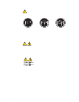 10
10 11
11 12
12 13
13 14
14 15
15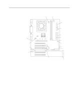 16
16 17
17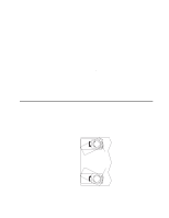 18
18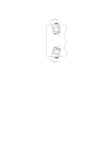 19
19 20
20