IBM 84885BU User Manual - Page 29
Erasing, forgotten, password, clearing
 |
View all IBM 84885BU manuals
Add to My Manuals
Save this manual to your list of manuals |
Page 29 highlights
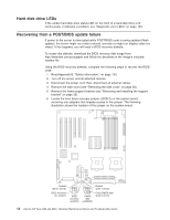
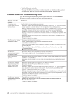
7. Remove the boot block recovery jumper from pins 1 and 2 and set the jumper in a safe place. 8. Replace any adapters that were removed. 9. Replace the frame-support bracket (see "Removing and installing the support bracket" on page 32). 10. Replace the side cover (see "Removing the side cover" on page 28). 11. Connect the server to a power source, keyboard, monitor, and mouse. 12. If the diskette drive contains a diskette, remove it. 13. Insert into the diskette drive the BIOS recovery diskette that you have created from http://www.ibm.com/pc/support/. 14. Turn on the server and the monitor. 15. After the update session is completed, turn off the server and monitor. 16. Remove the diskette from the diskette drive. 17. Disconnect all power cords and external cables; then, remove the side cover. 18. Remove the side cover. 19. Remove the frame-support bracket. 20. Remove any adapters that impede access to the jumper block. 21. Replace the boot block recovery jumper onto pins 1 and 2. 22. Replace any adapters that were removed. 23. Replace the frame-support bracket. 24. Reinstall the side cover. 25. Reconnect all external cables and power cords and turn on the peripheral devices. 26. Turn on the server to restart the operating system. Erasing a lost or forgotten password (clearing CMOS) This section applies to lost or forgotten passwords. For general information about passwords, see the User's Guide on the IBM Documentation CD. Complete the following steps to set the CMOS recovery jumper and erase a forgotten password: 1. Read Appendix B, "Safety information," on page 143 and "Handling static-sensitive devices" on page 26. 2. Turn off the server and all attached devices. 3. Disconnect the power cord, and disconnect all external cables. 4. Remove the side cover (see "Removing the side cover" on page 28). 5. Remove the support bracket (see "Removing and installing the support bracket" on page 32). 6. Locate the CMOS recovery jumper (JCMOS1) on the system board, removing any adapters or other components that impede access to the jumper. The following illustration shows the location of the jumper on the system board. Chapter 3. Diagnostics 19
-
 1
1 -
2
-
3
-
4
-
5
-
6
-
7
-
8
-
9
-
10
-
11
-
12
-
13
-
14
-
15
-
16
-
17
-
18
-
19
-
20
-
21
-
22
-
23
-
 24
24 -
 25
25 -
 26
26 -
 27
27 -
 28
28 -
 29
29 -
 30
30 -
 31
31 -
 32
32 -
 33
33 -
 34
34 -
35
-
36
-
37
-
38
-
39
-
40
-
41
-
42
-
43
-
44
-
45
-
46
-
47
-
48
-
49
-
50
-
51
-
52
-
53
-
54
-
55
-
56
-
57
-
58
-
59
-
60
-
61
-
62
-
63
-
64
-
65
-
66
-
67
-
68
-
69
-
70
-
71
-
72
-
73
-
74
-
75
-
76
-
77
-
78
-
79
-
80
-
81
-
82
-
83
-
84
-
85
-
86
-
87
-
88
-
89
-
90
-
91
-
92
-
93
-
94
-
95
-
96
-
97
-
98
-
99
-
100
-
101
-
102
-
103
-
104
-
105
-
106
-
107
-
108
-
109
-
110
-
111
-
112
-
113
-
114
-
115
-
116
-
117
-
118
-
119
-
120
-
121
-
122
-
123
-
124
-
125
-
126
-
127
-
128
-
129
-
130
-
131
-
132
-
133
-
134
-
135
-
136
-
137
-
138
-
139
-
140
-
141
-
142
-
143
-
144
-
145
-
146
-
147
-
148
-
149
-
150
-
151
-
152
-
153
-
154
-
155
-
156
-
157
-
158
-
159
-
160
-
161
-
162
-
163
-
164
-
165
-
166
-
167
-
168
-
169
-
170
-
171
-
172
-
173
-
174
-
175
-
176
-
177
-
178
-
179
-
180
-
181
-
182
-
183
-
184
-
185
-
186
-
187
-
188
-
189
-
190
-
191
-
192
-
193
-
194
-
195
-
196
-
197
-
198
-
199
-
200
 |
 |
