Icom IC-F4400D Instructions - Page 2
PANEL DESCRIPTION, FUNCTION DISPLAY, BATTERY CHARGING, Rapid charging with the BC-227, BASIC - ic f4400ds
 |
View all Icom IC-F4400D manuals
Add to My Manuals
Save this manual to your list of manuals |
Page 2 highlights
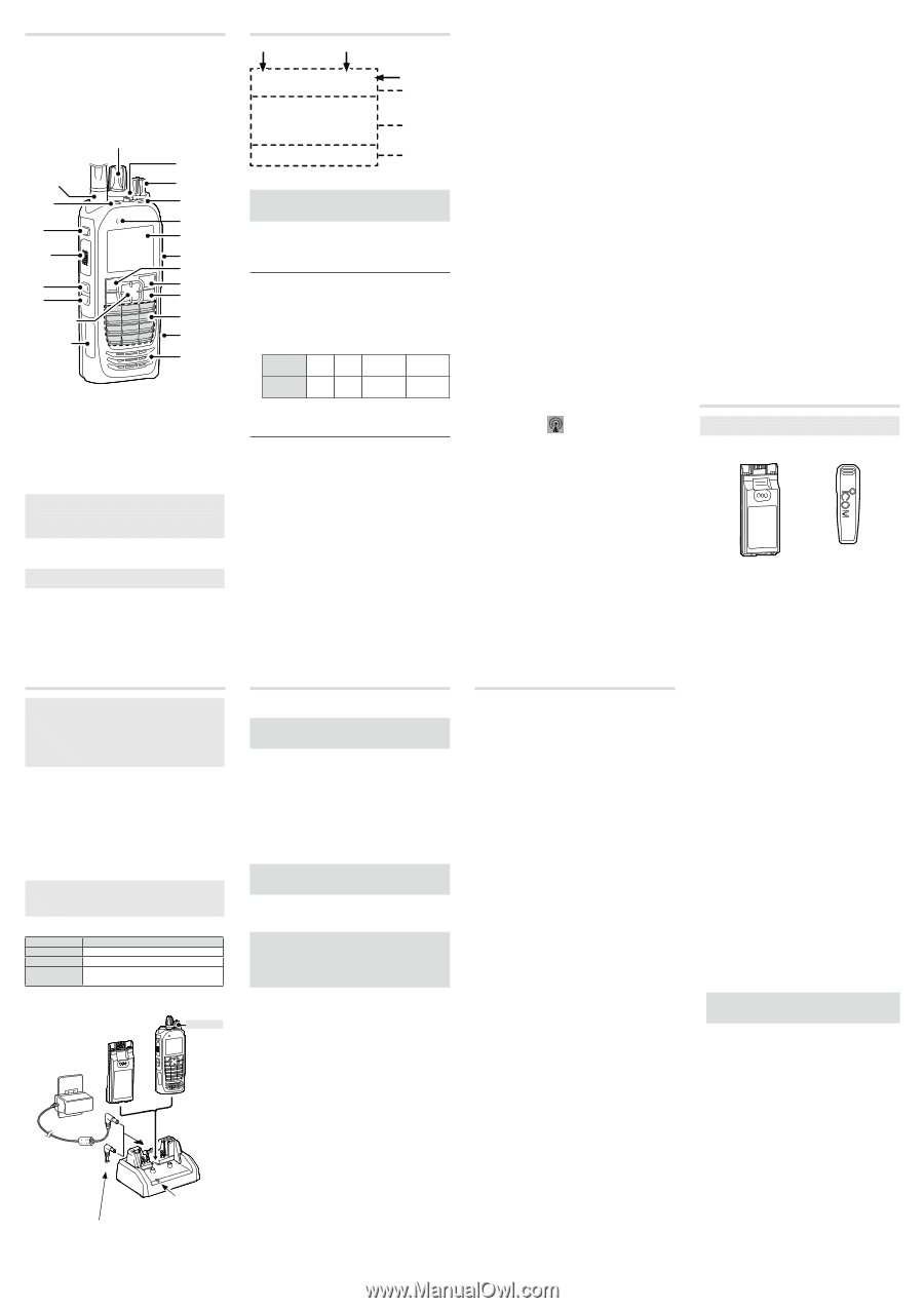
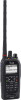
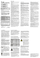
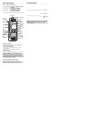
PANEL DESCRIPTION There are 3 types of transceivers. Non-display types: IC-F3400D, IC-F4400D, IC-F3400DP, IC-F4400DP Simple key types: IC-F3400DS, IC-F4400DS, IC-F3400DPS, IC-F4400DPS Ten-key types: IC-F3400DT, IC-F4400DT, IC-F3400DPT, IC-F4400DPT The illustration below shows the Then-key type transceiver. Antenna Connector [Emer] [F1] [PTT] [OK] [F2] [F3] [Up]/[Down] [Right]/[Left] USB Connector [Selector] Lever Switch [VOL] Status indicator Microphone Function Display Multiconnector [P1] [P2] [Back] Ten-Key Pad microSD Card Slot Speaker D Status indicator • Lights white, then blinks red, yellow, and green when turning ON the transceiver. • Lights red while transmitting. • Lights green while receiving a signal, or when the squelch is open. • Blinks magenta when the battery is exhausted. D Multi-connector Connects to an optional speaker microphone or headset. CAUTION: DO NOT use the transceiver without the connector cover or the optional equipment attached. The transceiver meets IP68 requirements for dust-tight and waterproof protection only when the connector cover or the optional HM-222 is attached. D About the Software key functions NOTE: Your dealers can assign the Software key functions to the keys, keypads, and the Lever switch. FUNCTION DISPLAY 1 2 3 Icon Area Text Area Key Display Area NOTE: The screen capture is an example.The displayed position of each icon may differ, depending on the function being used. D Icon Area Indicators 1 SIGNAL STRENGTH INDICATOR Displays the relative receive signal strength level. 2 CLOCK Displays the current time. "AM" or "PM" is displayed beside the time display when 12 hour display format is selected. 3 BATTERY INDICATOR Displayed or blinks to indicate the battery status. Indication Battery status Full Mid Charging Battery required exhausted blinks when the battery is exhausted. Icons * These icons are not displayed, depending on the presetting. POWER ICON • "L1" is displayed when the output power is set to Low. • "L2" is displayed when the output power is set to Mid. • "H" is displayed when the output power is set to High. AUDIBLE ICON Displayed when the channel is in the 'audible' (unmuted) mode. MESSAGE ICON • Blinks after Messages (Message or Status Message) have been received. • Stops blinking when the screen is changed, or any key is pushed, but is displayed if unread messages are still in the Message memory. • Disappears when all messages in the Message memory have been read. BELL ICON Displayed when a matching signal is received, depending on the presetting. SCAN ICON • Displayed when a scan is paused. • Blinks while scanning. SCAN TARGET CHANNEL ICON Displayed when the channel is selected as a scan target channel. SCRAMBLER/ENCRYPTION ICON In the Analog mode: • Displayed when the Voice Scrambler function is ON. In the Digital mode: • Displayed when the Voice Encryption function is ON. • Blinks when decoding an encrypted signal. GPS ICON* • Displayed when valid position data is received. • Blinks when searching for satellites or calculating position data. RECORD ICON* Displayed when the Record function is ON. Blinks while recording audio. "R" is displayed when there is no microSD card's free space and cannot record audio. TALK AROUND ICON Displayed when the Talk Around function is ON. PHONE ICON • Displayed when the transceiver is connected to a telephone network on the selected channel. • Blinks while receiving a phone call. BROADCAST ICON Displayed when receiving a Broadcast Call. For only the IC-F3400DP and IC-F4400DP series transceivers. SITE LOCK ICON Displayed when the Site Lock function is ON. LONE WORKER ICON Displayed when the Lone Worker function is ON. MOTION SENSOR ICON Displayed when the Motion Sensor function is ON. NOISE CANCEL ICON Displayed when the Noise Cancel function is ON. SURVEILLANCE ICON Displayed when the Surveillance function is ON. VIBRATION ICON Displayed when the Vibration function is ON. VOX ICON Displayed when the VOX function is ON. Bluetooth® ICON • Displayed when Bluetooth® is activated. • Lights Blue when a Bluetooth® device is connected. • Does not light when no Bluetooth® device is connected. microSD ICON* Displayed when the microSD card is inserted into the card slot. "R" is displayed when the microSD card has not been formatted. USB ICON Displayed when a USB device is connected. D Text Area Displays the selected Zone number, Channel number, and Channel name, if set. D Key Display Area Displays the names of the function assigned to [P1] and [P2]. Ask your dealer about the assigned Software key functions. SUPPLIED ACCESSORIES NOTE: Some accessories are not supplied, or the shape is different, depending on the transceiver version. Battery pack Belt clip BATTERY CHARGING NOTE: • Before detaching or attaching a battery pack, BE SURE to turn OFF the transceiver by rotating [VOL] fully counter clockwise, until it makes a "click" sound. Otherwise, a transceiver malfunction could occur. • The internal clock will be reset to 00:00 if an exhausted battery is left in the transceiver, or the battery pack is detached, for long periods of time. D Rapid charging with the BC-227 You can rapidly charge the Li-ion battery pack with the BC-242, BC-123S. Charging time: Approximately 4.4 hours for the BP-303 Additionally needed item (purchase separately): A power adapter (may be supplied with the charger, depending on the charger version) or the OPC-515L/ CP-23L DC POWER CABLES. CAUTION: DO NOT reverse the polarity when connecting the OPC-515L to a power source. This will ruin the battery charger. White line: +, Black line: _ Status indicator Light color Status Orange Charging Green Charging is completed. Blinks orange Charging failed. It mat have some and green problems. Battery pack Battery pack + Transceiver Turn OFF Power adapter* BC-227 Status indicator The OPC-515L* (for a 13.8 V power source) or the CP-23L (for a 12 V cigarette lighter socket) can be used instead of the power adapter. * A different type, or no power adapter is supplied, depending on the charger version. BASIC OPERATION D Turning ON the transceiver NOTE: Before using the transceiver for the first time, the battery pack must be fully charged for optimum life and operation. See the BATTERY CHARGING section of this sheet. Rotate [VOL] to turn ON the transceiver. D Receiving and Transmitting Receiving: 1. Select a channel. Rotate [Selector]. Push [Up] or [Down]. 2. When receiving a call, rotate [VOL] to adjust the audio output level to a comfortable listening level. Transmitting: CAUTION: Attach an antenna before transmitting. Transmitting without an antenna may damage the transceiver. 1. Wait until the channel is clear to avoid interference. 2. While holding down [PTT], speak at your normal voice level. 3. Release [PTT] to receive. IMPORTANT: To maximize the readability of your signal: 1. After pushing [PTT], pause briefly before you start speaking. 2. Hold the microphone 5 ~ 10 cm (2 ~ 4 inches) from your mouth, then speak at your normal voice level. OPTIONS D BATTERY PACKS • BP-283*1 Li-ion BATTERY PACK Voltage: 7.2 V Capacity: 1910 mAh (minimum), 2010 mAh (typical) Battery life: Approximately 10.5 hours • BP-284*1 Li-ion BATTERY PACK Voltage: 7.2 V Capacity: 3070 mAh (minimum), 3210 mAh (typical) Battery life: Approximately 16.5 hours • BP-303*1 Li-ion BATTERY PACK Voltage: 7.2 V Capacity: 3200 mAh (minimum), 3350 mAh (typical) Battery life: Approximately 16.5 hours *1 When the power save function is set to "Short," and the operating periods are calculated under the following conditions: TX : RX : standby = 5 : 5 : 90 D CHARGERS • BC-219 DESKTOP CHARGER + BC-123S AC ADAPTER For rapidly charging of battery packs. Charging time: Approximately 2.8 hours for the BP-283 A power adapter may be supplied, depending on the charger's version. • BC-227 DESKTOP CHARGER + BC-123S, BC-242 AC ADAPTER, OPC-515L DC POWER CABLE For rapidly charging of battery packs. Charging time: Approximately 4.4 hours for the BP-303 A power adapter may be supplied, depending on the charger's version. • BC-214 MULTI-CHARGER + BC-157S AC ADAPTER, OPC-656 DC POWER CABLE For rapidly charging of up to 6 battery packs simultaneously. Charging time: Approximately 2.8 hours for the BP-283 The AD-130 CHARGER ADAPTER may be needed, depending on the charger's version. The BC-157S AC ADAPTER or OPC-656 DC POWER CABLE must be purchased separately. • BC-225 INTELLIGENT DESKTOP CHARGER + BC-123S AC ADAPTER For rapidly charging of battery packs. Charging time: Approximately 2.5 hours for the BP-283 • BC-226 MULTI-CHARGER + BC-228 AC ADAPTER For rapidly charging of up to 6 battery packs simultaneously. Charging time: Approximately 4.2 hours for the BP-303 The BC-228 AC ADAPTER must be purchased separately. D DC CABLES • CP-23L CIGARETTE LIGHTER CABLE Used for charging battery packs through a 12 V cigarette lighter socket. For use with the BC-219. • OPC-515L, OPC-656 DC POWER CABLES Used for charging battery packs using a 13.8 V DC power source instead of the power adapter. OPC-515L: For the BC-219 OPC-656: For the BC-214 D BELT CLIPS and BELT HANGERS • MB-133 BELT CLIP • MB-136 BELT CLIP: Rotating type. • MB-96F, MB-96FL, MB-96N BELT HANGERS D ANTENNAS • FA-S81VS, FA-S82VS, FA-S83VS, FA-S81US, FA-S82US STUBBY ANTENNAS Shorter VHF or UHF antennas. FA-S81VS: 136 ~ 150 MHz, FA-S82VS: 148 ~ 162 MHz FA-S83VS: 160 ~ 174 MHz, FA-S81US: 400 ~ 450 MHz FA-S82US: 450 ~ 490 MHz • FA-S81V, FA-S82V, FA-S83V, FA-S81U, FA-S82U, FA-S83U FLEXIBLE ANTENNAS VHF or UHF antennas. FA-S81V: 136 ~ 150 MHz, FA-S82V: 148 ~ 162 MHz FA-S83V: 160 ~ 174 MHz, FA-S81U: 380 ~ 430 MHz FA-S82U: 430 ~ 480 MHz, FA-S83U: 470 ~ 520 MHz • FA-S67VC, FA-S76UC CUT ANTENNAS FA-S67VC: 136 ~ 174 MHz, FA-S76UC: 380 ~ 520 MHz D OTHERS • AD-118 ACC ADAPTER To connect an accessory. See the AD-118 instruction sheet for details of recommended accessories. CAUTION: The AD-118 does not have waterproof protection. When it is connected, NEVER expose the adapter and the transceiver to rain, snow or any liquids. • LC-184, LC-186 CARRYING CASE LC-184: For the Simple key and Ten-key transceivers LC-186: For the Non-display transceivers • VS-4MC PTT SWITCH CABLE + HS-94, HS-95, HS-97 HEADSET VS-4MC: To connect a headset to a transceiver. (Non-waterproof) HS-94: Ear-hook type HS-95: Neck-arm type HS-97: Throat microphone • HM-222, HM-222H SPEAKER MICROPHONE With an Emergency key, meets IP68 requirements for dust-tight and waterproof protection. HM-222: Speaker microphone HM-222H: High audio output type High audio output is only usable with transceivers that support the function. (With a "U" mark on the serial number label) • VS-3 Bluetooth® HEADSET The Bluetooth headset with a [PTT] switch. • About the third party Bluetooth® headsets: Icom has checked the PTT operation with some 3M Peltor headsets such as the WS Headset XP, WS ProTac XP and WS Alert XP. (Compatibility not guaranteed.) • UT-134 AES/DES ENCRYPTION UNIT Some options may not be available in some countries. Ask your dealer for details.
-
 1
1 -
 2
2 -
 3
3
 |
 |