Icom IP501M Instruction Manual - Page 2
Panel Description, Rear Panel Connection, Basic Operation, Mounting The Transceiver
 |
View all Icom IP501M manuals
Add to My Manuals
Save this manual to your list of manuals |
Page 2 highlights
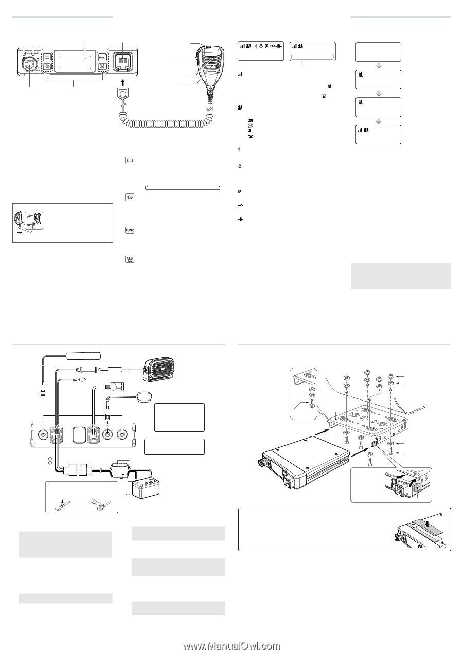
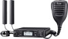
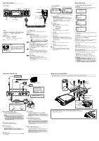
PANEL DESCRIPTION D Front Panel Indicators [TX/RX] [MSG] Function display Microphone jack IP501M [DIAL] Operating keys Option key [PTT] Microphone Speaker D DIAL Hold down for 1 second to turn the transceiver ON or OFF. • On standby screen: Rotate to adjust the audio volume. • Others: Rotate to select an item. D Indicators [TX/RX] Lights red: Transmitting Lights green: Receiving Lights orange: Receiving and transmitting [MSG] Reserved for a future function. MICROPHONE HANGER Connect the microphone hanger to the vehicle's ground for microphone ON/OFF hook functions when the HM-241/HM-230HB microphone is used. User supplied D Operating keys Assigned key functions may differ, depending on the presetting. [Address] key • Selects a preset address. • Push to toggle the address book between the call types. You can also toggle the address by rotate [DIAL]. All → Group (Talkgroup) → Individual [Call History] key • Push to display the call history. • Push this key several times to toggle between the Call his types, Transmitted call, Received call, Sent message, and Received message. • Hold down until "Emergency" is displayed to send an Emergency call. [FUNC] key • Push to select a Message, Status, Talkgroup, Bluetooth Pairing, UTC Offset function, Bluetooth One Touch PTT function, or Network Operator. • Hold down for 3 seconds to enter the Set Mode function. [CLR/Lock] key • Push to return to the standby screen. • Hold down for 1 second to turn the Key Lock function ON or OFF. [PTT] and [DIAL] are usable even while the Key Lock function is ON. D Function Display Standby screen Example: When receiving a custom message 10/14 12:00 All 10/14 13:00 Everyone meet NOW Scrolls, depending on the message length : Signal strength The signal strength is represented by 3 bars. When the transceiver location is out of the service area, or cannot receive the control signal, the (out-of-area) icon blinks. If the IP501M has not been authenticated, is displayed. : Call types Shows the call type. Blinks when a call or message is received. : All/Group Call : Talkgroup Call* : Individual Call : Phone Call* * May be usable, depending on a presetting. : Bluetooth Displayed when the transceiver is connected to Bluetooth device. : Pocket beep • Displayed when the Pocket Beep function is ON. • Blinks when a call is received. This icon blinks until the transceiver return to the standby mode after a received signal disappears. : P-Bell Displayed when the P-Bell function is used. : Key Lock Displayed when Key Lock function is ON. : GPS • Displayed when valid position data is received. • Blinks when searching for satellites or calculating position data. BASIC OPERATION D Turning the transceiver ON or OFF Turning ON: Hold down [DIAL] for 1 second to turn ON the transceiver. • The standby screen is displayed as follows: IP501M Ver. x.x.xx/x Connecting... 00002 Setting up... 00002 10/14 12:00 All It may take a few minutes to boot up the transceiver for the first time. Turning OFF: Hold down [DIAL] for 1 second to turn OFF the transceiver. D Receiving and Transmitting Receiving: When a Call is received, the [TX/RX] indicator lights green. Rotate [DIAL] to adjust the audio output level to a comfortable listening level. When the volume is "0," key beeps and ringer tones do not sound. Transmitting: While holding down [PTT], speak at your normal voice level. • The [TX/RX] indicator lights red while [PTT] is pushed. Talk while receiving a call: While receiving a call, push [PTT] to talk in the Full-Duplex mode* like a telephone call. • In the Full-Duplex mode, the [TX/RX] indicator lights orange. Rotate [DIAL] to adjust the audio output level. DO NOT cover the speaker or microphone. * Depends on a presetting. Ask your dealer for details. IMPORTANT: To maximize the readability of your signal: 1. After pushing [PTT], pause briefly before you start speaking. 2. Hold the microphone 5 ~ 10 cm (2 ~ 4 inches) from your mouth, then speak at your normal voice level. REAR PANEL CONNECTION MOUNTING THE TRANSCEIVER The universal mounting bracket supplied with your transceiver enables various mounting positions. • Mount the transceiver securely with the 4 supplied screws to a thick surface which can support more than 1.5 kg (3.3 lb). Optional speaker 1 23 7 Red Black 456 1 TIP: After connecting the LTE Antennas and GPS Antenna, wrap the connectors with rubber vulcanizing tape to help in waterproofing. R WARNING! NEVER remove the fuse holders from the DC power cable. Fuse holders NOTE: Use the terminals as shown below for the cable connections. Crimp Solder 1 LTE ANTENNA CONNECTORS Connect to the supplied LTE antenna. Contact your dealer about antenna placement. NOTE: • Keep at a distance of 30 cm (12 inches) or more between the LTE antennas during operation. • Be sure the LTE antennas are positioned where they have a clear view to receive signal, and fixed using the adhesive pad. 2 EXTERNAL SPEAKER JACK Connect a 4 ~ 8 Ω external speaker. 3 IGNITION LEAD Connect to an ignition line. CAUTION: DO NOT put pressure on this lead. Binding to the DC power cable is recommended. 4 D-Sub 25-pin Remove the cover and connect the optional OPC-2407 ACC CABLE. 12 V or 24 V Battery 5 LAN CABLE Connect the network devices such as a switch. CAUTION: DO NOT connect other than network devices, such as microphone. This could damage the transceiver. 6 GPS ANTENNA CONNECTOR Connect the supplied GPS antenna. NOTE: Be sure the GPS antenna is positioned where the GPS antenna has a clear view to receive signal from satellites, and fixed using the supplied doublesided adhesive pad. 7 DC POWER CONNECTOR Connect to a 12 V/24 V DC battery. Pay attention to polarities. Red line: +, Black line: _ CAUTION: DO NOT reverse the DC power cable polarity when connecting to a power source. This could damage the transceiver. Self-tapping screws Mounting bracket Nuts Flat washers Spring washers Mounting screws When removing, slide the transceiver towards you while push the lever. Lever To reduce vibration, place the cushion on the transceiver and put the sheet on it. When mounting the bracket on the bottom side, attach a cushion and a sheet to the bottom of the transceiver. Sheet Cushion
-
 1
1 -
 2
2
 |
 |