Icom VE-PG3 Installation Guide - Page 2
Step 4, Con the VE-PG3 - instruction manual
 |
View all Icom VE-PG3 manuals
Add to My Manuals
Save this manual to your list of manuals |
Page 2 highlights
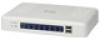
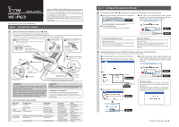
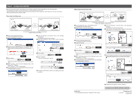
Step 4 Configure the VE-PG3 Select the Converter mode or the Bridge mode, and then configure the ports according to your operating needs. • The following is an example of connecting the radio to [TRX1] (upper slot) on the VE-PG3. • When the operating mode or setting of the port (to connect the radio) has been changed, the related settings are returned to their default. • See the VE-PG3 instruction manual for details. When using in the Bridge mode Area A Area B Radio A [TRX1] IP Network Radio B [TRX1] Radio A1(Extension) VE-PG3 (192.168.0.2) VE-PG3 (192.168.0.3) An example of communication in the Bridge's unicast mode. (Radio to radio communication) Radio B1(Extension) q Click the [Operating Mode] menu. • The [Operating Mode] screen appears. w Verify that [Bridge] is selected. u Click the [Bridge Connection] menu, then [Bridge Connection]. • The [Bridge Connection] screen appears. i Enter the IP address of the VE-PG3 in area B (example :192.168.0.3). Verify e Select [Unicast] for the port (example: Transceiver 1 (TRX1)). • When using in the Multicast mode, you can skip this step. Verify that the port to connect the radio is selected. Enter Select r Click . Click • When you are asked to reboot the VE-PG3, follow the instructions. t After rebooting, click the [Port Settings] menu, then [Transceiver 1 (TRX1)]. • The [Transceiver 1 (TRX1)] screen appears. y Verify that the radio to be connected to the port (example: IC-F5060/F6060) is selected. Verify o Click . !0 Click . • Verify that "During transmit" appears. Click q Click w Verify !1 Configure the VE-PG3 in area B, by following the same procedure. When using in the Converter mode Area A Extension number 301 [TRX1] [LAN] IP Network Area B HUB Extension number 401 Radio A Radio A1(Extension) VE-PG3 (192.168.0.2) SIP phone (KX-UT123/KX-UT136 series) An example of communication in the Converter mode. (Radio to IP telephone communication) q Click the [Network] menu, then [DHCP Server]. • The [DHCP Server] screen appears. w Select "Enable," and then click . i Click the [Extension Connect] menu, then [Extension Connect]. • The [Extension Connect] screen appears. o Enter radio A's extension number, default call destination number and so on, and then click . q Configure Select e Click the [Operating Mode] menu. • The [Operating Mode] screen appears. r Select [Converter]. Click Select t Click . Click • When you are asked to reboot the VE-PG3, follow the instructions. y After rebooting, click the [Port Settings] menu, then [Transceiver 1 (TRX1)]. • The [Transceiver 1 (TRX1)] screen appears. u Verify that the radio to be connected to the port (example: IC-F5060/F6060) is selected. w Click • The radio A's call setting is added on [List of Extension Entries]. Added !0 Enter IP Telephone's extension number, default call destination number, MAC address and so on, and then click . Verify q Configure 1-1-32 Kamiminami, Hirano-ku, Osaka 547-0003, Japan w Click • The IP Telephone's call setting is added on [List of Extension Entries]. Added !1 Initialize the IP telephone ("Factory Setting"). Continued on the "INSTALLATION 2" leaflet.Î A-7046W-3EX Printed in Japan © 2012 Icom Inc.
-
 1
1 -
 2
2
 |
 |