Image Fitness 3.6 Bench English Manual - Page 7
Note: Tighten all the M10 Nylon Locknuts 11
 |
View all Image Fitness 3.6 Bench manuals
Add to My Manuals
Save this manual to your list of manuals |
Page 7 highlights
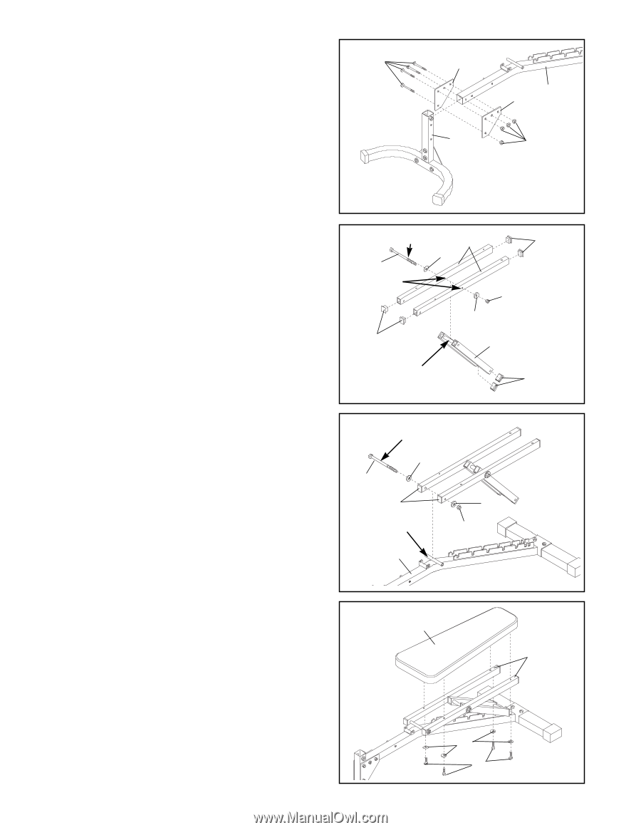
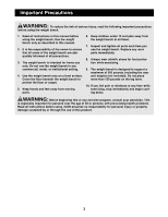
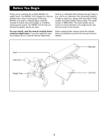
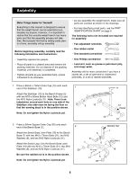
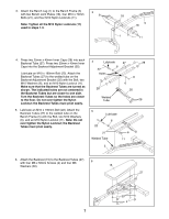
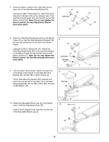
3. Attach the Bench Leg (1) to the Bench Frame (5) with two Bench Joint Plates (18), four M10 x 70mm Bolts (21), and four M10 Nylon Locknuts (11). Note: Tighten all the M10 Nylon Locknuts (11) used in steps 1-3. 3 21 18 5 18 1 11 4. Press two 25mm x 40mm Inner Caps (28) into each Backrest Tube (27). Press two 25mm x 40mm Inner Caps into the Backrest Adjustment Bracket (35). Lubricate an M10 x 190mm Bolt (22). Attach the Backrest Tubes (27) to the welded tube on the Backrest Adjustment Bracket (35) with the Bolt, two M10 Washers (6), and an M10 Nylon Locknut (11). Make sure that the Backrest Tubes are turned as shown. The indicated holes are not centered in the Backrest Tubes but are closer to one side. Turn the Backrest Tubes so the holes are closer to the floor. Do not over tighten the Nylon Locknut; the Backrest Tubes must pivot easily. 5. Lubricate an M10 x 190mm Bolt (22). Attach the Backrest Tubes (27) to the welded tube on the Bench Frame (5) with the Bolt, two M10 Washers (6), and an M10 Nylon Locknut (11). Note: Do not over tighten the Nylon Locknut; the Backrest Tubes must pivot easily. 4 Lubricate 27 28 6 22 Holes 11 6 28 35 Welded Tube 28 5 22 Lubricate 6 27 Welded Tube 6 11 5 6. Attach the Backrest (15) to the Backrest Tubes (27) with four M6 x 55mm Screws (4) and four M6 6 Washers (30). 15 27 30 4 7
-
 1
1 -
 2
2 -
 3
3 -
 4
4 -
 5
5 -
 6
6 -
 7
7 -
 8
8 -
 9
9 -
 10
10 -
 11
11 -
 12
12 -
13
-
14
-
15
-
16
 |
 |