Image Fitness 8.5 Elliptical English Manual - Page 7
Handlebar Leg with two M8 x 45mm Button Bolts 50
 |
View all Image Fitness 8.5 Elliptical manuals
Add to My Manuals
Save this manual to your list of manuals |
Page 7 highlights
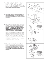
5. The Console (5) requires four "D" batteries (not included); alkaline batteries are recommended. Remove the indicated screw from the battery drawer, and pull the battery drawer open. Insert four batteries into the battery drawer; make sure that the batteries are oriented as shown by the markings inside the battery drawer. Close the battery drawer and reattach the screw. Note: When the batteries are installed correctly, the fan will turn on for a moment. 6. Identify the Left Handlebar (9), which is marked with a sticker. Insert the Left Handlebar into one of the Handlebar Legs (79); make sure that the Handlebar Leg is turned so the hexagonal holes are on the indicated side. Attach the Left Handlebar to the Handlebar Leg with two M8 x 45mm Button Bolts (50) and two M8 Nylon Locknuts (46). Make sure that the Nylon Locknuts are inside of the hexagonal holes. Do not tighten the Button Bolts yet. Apply a generous amount of the included grease to the Pivot Axle (97) and to the two M8.5 Washers (53). Next, insert the Pivot Axle into the Upright (2) and centre it. Reapply grease to both ends of the Pivot Axle. Slide a Handlebar Spacer (25) onto the short tube on the Left Handlebar (9), and rotate the Handlebar Spacer so the small arrow is pointing toward the floor. Next, slide the Left Handlebar onto the left end of the Pivot Axle (97). Finger tighten an M8 x 25mm Patch Screw (22) with an M8.5 Washer (53) and a Wave Washer (95) into the end of the Pivot Axle. Then, press the small tabs on a Handlebar Cap (23) into the Handlebar Spacer. Assemble the Right Handlebar (not shown) and the other Handlebar Leg (not shown) in the same way. Tighten both M8 x 25mm Patch Screws (22) at the same time. 7. Hold the lower end of the left Handlebar Leg (79) inside of the left Front Flex Bracket (17). Apply a small amount of grease to an M10 x 78mm Button Bolt (27). Attach the left Handlebar Leg to the left Front Flex Bracket with the Button Bolt, two M10 Washers (38), and an M10 Nylon Locknut (29). Do not overtighten the Nylon Locknut; the left Handlebar Leg must be able to pivot freely. Attach the right Handlebar Leg (79) to the right Front Flex Bracket (17) in the same way. See step 6. Tighten the M8 x 45mm Button Bolts (50) in the Handlebar Legs (79). See step 3. Tighten the M10 x 88mm Button Screw (63). 5 5 Batteries Screw 6 Battery Drawer Grease 9 Tube 53 22 97 2 25 Arrow 95 46 23 50 Hexagonal Holes 79 7 79 29 38 38 27 17 Grease 79 17 7
-
 1
1 -
 2
2 -
 3
3 -
 4
4 -
 5
5 -
 6
6 -
 7
7 -
 8
8 -
 9
9 -
 10
10 -
 11
11 -
 12
12 -
13
-
14
-
15
-
16
-
17
-
18
-
19
-
20
-
21
-
22
-
23
-
24
 |
 |
