Image Fitness 923 English Manual - Page 6
Image Fitness 923 Manual
 |
View all Image Fitness 923 manuals
Add to My Manuals
Save this manual to your list of manuals |
Page 6 highlights
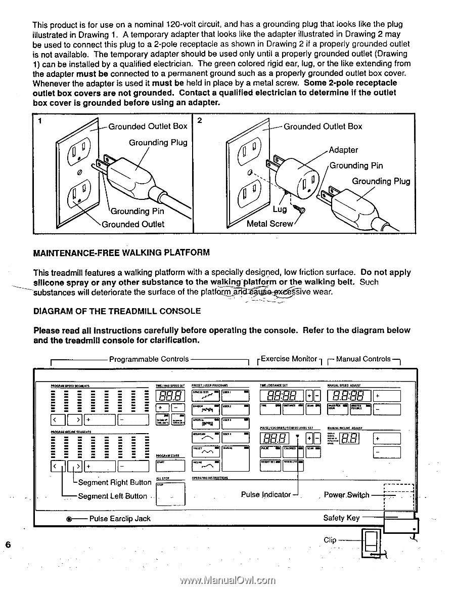
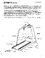
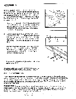
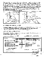
This product is for use on a nominal 120-volt circuit, and has a grounding plug that looks like the plug illustrated in Drawing 1. A temporary adapter that looks like the adapter illustrated in Drawing 2 may be used to connect this plug to a 2-pole receptacle as shown in Drawing 2 if a properly grounded outlet is not available. The temporary adapter should be used only until a properly grounded outlet (Drawing 1) can be installed by a qualified electrician. The green colored rigid ear, lug, or the like extending from the adapter must be connected to a permanent ground such as a properly grounded outlet box cover. Whenever the adapter is used it must be held in place by a metal screw. Some 2-pole receptacle outlet box covers are not grounded. Contact a qualified electrician to determine if the outlet box cover is grounded before using an adapter. 1 2 Grounded Outlet Box Grounded Outlet Box 0g I 0 Grounding Plug ° Grounding Pin Grounded Outlet e a., 0 ° Lug Metal Screw Adapter Grounding Pin g Grounding Plug MAINTENANCE-FREE WALKING PLATFORM This treadmill features a walking platform with a specially designed, low friction surface. Do not apply silicone spray or any other substance to the walking-platform or the walking belt. Such substances will deteriorate the surface of the platfarl_Wtfie fiive wear. DIAGRAM OF THE TREADMILL CONSOLE Please read all instructions carefully before operating the console. Refer to the diagram below and the treadmill console for clarification. Programmable Controls I r Exercise Monitor1 Manual Controls PROGRAM SPEED SEGMENTS PROGRAM INCLINE SEGMENTS TMEE MAX SPEED SET nouo.uo PRESET] USER PROGRAMS null 11.0041 BM WERT r IMPI TIME / DISTANCE SET MANUAL SPEED ADJUST MM uoon•.onuo Fa p a on TuT MIAMI In ACM On MILESPEA Ell 'MIMS MI PEA IKE IMIIIWAL OfT NWMM MINIM MM USER. MM PULSE I CALORIES I FITNESS LEVEL SET oann on • CB MANUAL INCLINE ADJUST BB WM, 1.0.1 PROGRAM START VALUI. ts../N MANUAL MK MI CALORIES RCM I= STMT *WOE NEWT SET In MMUUN a Segment Right Button ALL STOP S101. Segment Left.Button . OPERATING INSTRUCTIONS r 1 Pulse ln.dicator- . , Power.Switph .4 .1 r ' Pulse Earclip Jack Safety Key 6 Clip
-
 1
1 -
 2
2 -
 3
3 -
 4
4 -
 5
5 -
 6
6 -
 7
7 -
 8
8 -
 9
9 -
 10
10 -
 11
11 -
 12
12 -
13
-
14
-
15
-
16
 |
 |