Image Fitness 935 Treadmill English Manual - Page 14
Model
 |
View all Image Fitness 935 Treadmill manuals
Add to My Manuals
Save this manual to your list of manuals |
Page 14 highlights
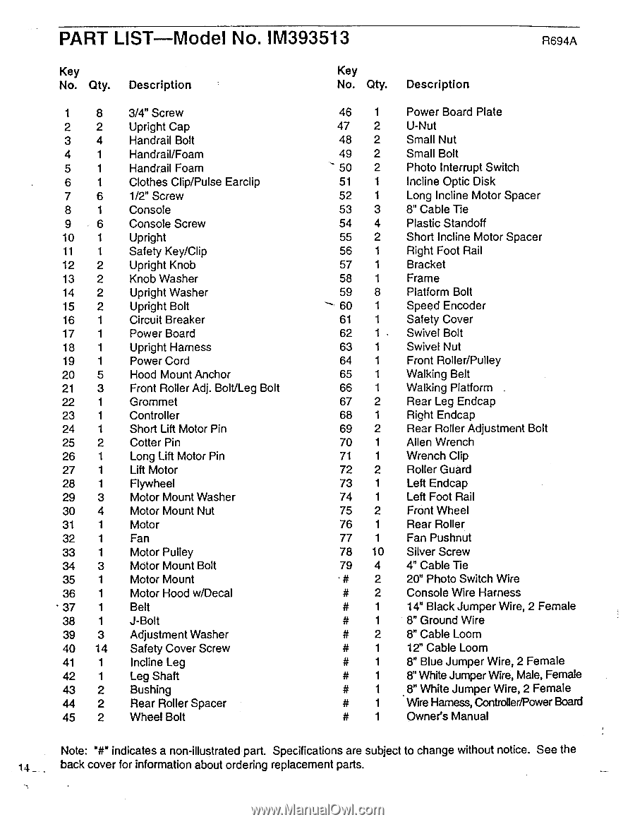
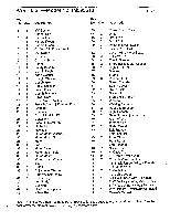
PART LIST Model No. IM393513 R694A Key No. Qty. Description Key No. Qty. Description 1 8 2 2 3 4 4 1 5 1 6 1 7 6 8 1 9 6 10 1 11 1 12 2 13 2 14 2 15 2 16 1 17 1 18 1 19 1 20 5 21 3 22 1 23 1 24 1 25 2 26 1 27 1 28 1 29 3 30 4 31 1 32 1 33 1 34 3 35 1 36 1 37 1 38 1 39 3 40 14 41 1 42 1 43 2 44 2 45 2 3/4" Screw Upright Cap Handrail Bolt Handrail/Foam Handrail Foam Clothes Clip/Pulse Earclip 1/2" Screw Console Console Screw Upright Safety Key/Clip Upright Knob Knob Washer Upright Washer Upright Bolt Circuit Breaker Power Board Upright Harness Power Cord Hood Mount Anchor Front Roller Adj. Bolt/Leg Bolt Grommet Controller Short Lift Motor Pin Cotter Pin Long Lift Motor Pin Lift Motor Flywheel Motor Mount Washer Motor Mount Nut Motor Fan Motor Pulley Motor Mount Bolt Motor Mount Motor Hood w/Decal Belt J-Bolt Adjustment Washer Safety Cover Screw Incline Leg Leg Shaft Bushing Rear Roller Spacer Wheel Bolt 46 1 47 2 48 2 49 2 50 2 51 1 52 1 53 3 54 4 55 2 56 1 57 1 58 1 59 8 60 1 61 1 62 1 63 1 64 1 65 1 66 1 67 2 68 1 69 2 70 1 71 1 72 2 73 1 74 1 75 2 76 1 77 1 78 10 79 4 # 2 # 2 # 1 # 1 # 2 # 1 # 1 # # 1 # 1 # 1 Power Board Plate U-Nut Small Nut Small Bolt Photo Interrupt Switch Incline Optic Disk Long Incline Motor Spacer 8" Cable Tie Plastic Standoff Short Incline Motor Spacer Right Foot Rail Bracket Frame Platform Bolt Speed Encoder Safety Cover Swivel Bolt Swivel Nut Front Roller/Pulley Walking Belt Walking Platform Rear Leg Endcap Right Endcap Rear Roller Adjustment Bolt Allen Wrench Wrench Clip Roller Guard Left Endcap Left Foot Rail Front Wheel Rear Roller Fan Pushnut Silver Screw 4" Cable Tie 20" Photo Switch Wire Console Wire Harness 14" Black Jumper Wire, 2 Female 8" Ground Wire 8" Cable Loom 12" Cable Loom 8" Blue Jumper Wire, 2 Female 8" White Jumper Wire, Male, Female 8" White Jumper Wire, 2 Female Wire Hamess, Controller/Power Board Owner's Manual Note: 'Wm indicates a non-illustrated part. Specifications are subject to change without notice. See the 14 _ back cover for information about ordering replacement parts.
-
 1
1 -
2
-
3
-
4
-
5
-
6
-
7
-
8
-
 9
9 -
 10
10 -
 11
11 -
 12
12 -
 13
13 -
 14
14 -
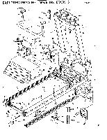 15
15 -
 16
16
 |
 |