Image Fitness Renew 400 Canadian English Manual - Page 11
Spa Shell Diagram
 |
View all Image Fitness Renew 400 manuals
Add to My Manuals
Save this manual to your list of manuals |
Page 11 highlights
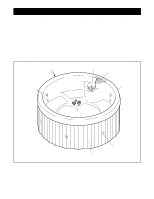
Spa Shell Diagram A D C E B SPA OPERATION Refer to the diagram above. The function of each component is explained below. The temperature probe (A) reads the current water temperature. The suction vents (B) located near the floor of the spa bring water into the pump in order to operate the system. The suction covers should always be in place over the suction vents. Never operate the spa without the suction covers in place. The filter (C) can be removed for cleaning and replacement (see CHECKING AND CLEANING THE FILTER on page 14). The console (D) is explained on page 12. The eight fixed jets (E) provide a relaxing water massage. The intensity of the massage can be adjusted using the air control (see page 12). 11
-
 1
1 -
2
-
3
-
4
-
5
-
 6
6 -
 7
7 -
 8
8 -
 9
9 -
 10
10 -
 11
11 -
 12
12 -
 13
13 -
 14
14 -
 15
15 -
 16
16 -
17
-
18
-
19
-
20
 |
 |

11
SPA OPERATION
Refer to the diagram above. The function of each
component is explained below.
The
temperature probe
(A) reads the current water
temperature.
The
suction vents
(B) located near the floor of the
spa bring water into the pump in order to operate the
system.
The suction covers should always be in
place over the suction vents. Never operate the
spa without the suction covers in place.
The
filter
(C) can be removed for cleaning and
replacement (see CHECKING AND CLEANING THE
FILTER on page 14).
The
console
(D) is explained on page 12.
The eight
fixed jets
(E) provide a relaxing water mas-
sage. The intensity of the massage can be adjusted
using the air control (see page 12).
Spa Shell Diagram
B
A
C
D
E