Insignia NS-39L700A12 Quick Setup Guide (English) - Page 1
Insignia NS-39L700A12 Manual
 |
View all Insignia NS-39L700A12 manuals
Add to My Manuals
Save this manual to your list of manuals |
Page 1 highlights
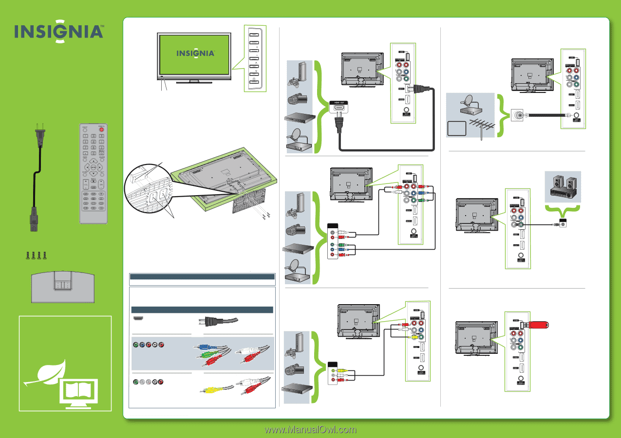
Front features MENU INPUT 39" LCD TV VOL VOL QUICK SETUP GUIDE CH NS-39L700A12 CH Thank You for purchasing this fine Insignia television. We hope you enjoy the quality and reliability of this product for years to come INP UT P OWE R 123 4 56 7 INF O 89 R E CALL 0 G UIDE Remote Power control sensor indicator Installing the stand 1 Carefully place your TV screen face-down on a cushioned, clean surface to protect the screen from damages and scratches. 2 Align the locating grooves on the stand with the locators on the stand column on the back of the screen, then secure the stand to the screen using the four M5 x 8 mm screws (provided). Locators Connecting a DVD or Blu-ray player, cable box, satellite receiver, camcorder, or game station Using an HDMI cable (best) USB COMPONENT IN R AUDIO PR L AV IN PB COAXIAL Y/ VIDEO HDMI 1 HDMI 2 ANT/ CABLE IN Note: Cable is not provided. Using component cables (better) ME NU E XIT MU T E VOL CH FAVOR ITE VIDE O HDMI TV C OMP MT S /S A P VGA ZOO M SLEEP CH-LIS T PICTUR E AUDIO CCD AC power cord Remote control with AAA batteries (2) Stand screws (4) TV stand WE ARE GOING GREEN! A copy of your User Guide is not provided in the box but is available online. Go to www.insigniaproducts.com, click Support & Service, enter your model number in the Product Search field, then click Search. Locating grooves Screws Installing a wall-mount bracket 1 Carefully place your TV screen face-down on a cushioned, clean surface to protect the screen from damages and scratches. 2 Remove the screws holding the TV to the stand column. 3 Remove the stand base and the stand column. 4 Abtatcakchoftyhoeuwr aTlVl-.mSeoeutnhtebirnasctkruetcttiooynosuthr TatVcuasminegwthitehmthoeuwnatiWlnl-gmarhonouilnnegst bornatchkeet for information about how to correctly hang your TV. Warning This apparatus is intended to be supported by a UL Listed wall-mount bracket. Identifying cables Your TV has several connection types for connecting devices. For the best video quality, connect a device to the best available connection. Connection type Video quality Cable connector HDMI video/audio Best OR Component video and analog audio Better OR Good Composite video and analog audio You can use the HDMI jack to connect a DVI device to your TV. You need to attach an HDMI-to-DVI adapter to the end of the HDMI cable that connects to the DVI device's jack. COMPONENT OUT USB COMPONENT IN R AUDIO PR L AV IN PB COAXIAL Y/ VIDEO HDMI 1 HDMI 2 ANT/ CABLE IN Note: Cable is not provided. Note: The COMPONENT IN video jacks share the audio jacks with the AV IN VIDEO jack. Cables are often color-coded to match color-coded jacks. Using composite cables (good) AUDIO/VIDEO OUT VIDEO L R USB COMPONENT IN R AUDIO PR L AV IN PB COAXIAL Y/ VIDEO HDMI 1 HDMI 2 ANT/ CABLE IN Note: Cable is not provided. Note: Connect your Yellow video cable to the Green Y/Video jack. AV IN AV IN AV IN AV IN AV IN AV IN Connecting an antenna/cable wall jack CABLE USB COMPONENT IN R AUDIO PR L AV IN PB COAXIAL Y/ VIDEO HDMI 1 HDMI 2 ANT/ CABLE IN Note: Cable is not provided. Connecting a home theater system USB COMPONENT IN R AUDIO PR L AV IN PB COAXIAL Y/ VIDEO HDMI 1 HDMI 2 ANT/ CABLE IN COAXIAL IN Note: Cable is not provided. Connecting a USB flash drive USB COMPONENT IN R AUDIO PR L AV IN PB COAXIAL Y/ VIDEO HDMI 1 USB flash drive HDMI 2 ANT/ CABLE IN Note: USB flash drive is not included.
-
 1
1 -
 2
2
 |
 |