Insignia NS-TVM101 Quick Setup Guide (English) - Page 1
Insignia NS-TVM101 Manual
 |
UPC - 600603126642
View all Insignia NS-TVM101 manuals
Add to My Manuals
Save this manual to your list of manuals |
Page 1 highlights
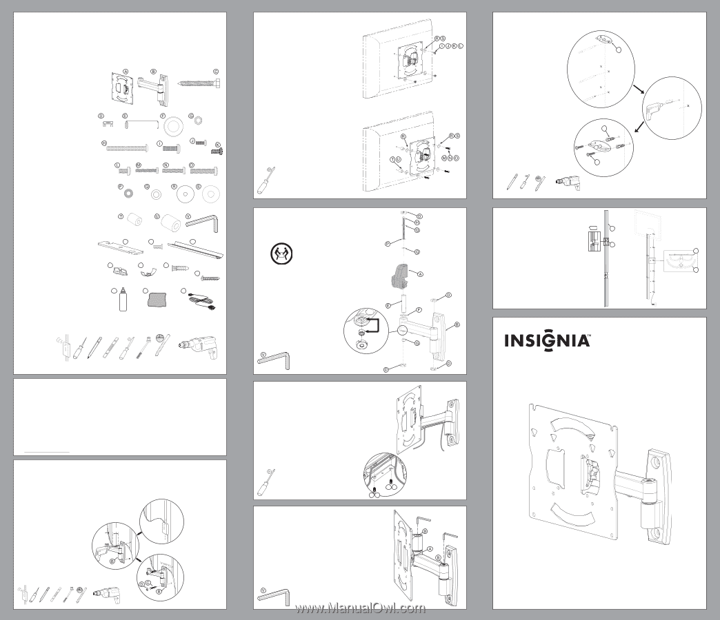
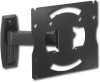
Welcome Thank you for your purchase of the NS-TVM101 wall mount. It is a full-motion mount that allows the TV or monitor to tilt ±15°, swivel ±15°, and extend 8.8 inches (22.4 cm) from the wall. The cable tunnels can hide cables and can be cut and painted to any desired size and color. PARTS LIST Before starting assembly, verify that all parts are included and undamaged. If any parts are missing or damaged, do not return the item to your dealer, but contact Customer Service. Never use damaged parts. Missing parts? Call (877) 467-4289. Note: Not all parts will be used A TV bracket (1) B Wall bracket (1) C Lag bolt (2) D Hinge caps (6) E Swivel head bearing (1) F Swivel head washer (1) G Swivel head nut (1) H 1/4" × 3.25" (82.6 mm) bolt (1) I M6× 0.78" (20 mm) bolt (4) J M4 × 0.47" (12 mm) bolt (4) K M5 × 0.47" (12 mm) bolt (4) L M6 × 0.47" (12 mm) bolt (4) M M4 × 1.18" (30 mm) bolt (4) N M5 × 1.18" (30 mm) bolt (4) O M6 × 1.38" (35 mm) bolt (4) P Plastic 0.5" (12.7 mm) washer (1) Q 0.5" (12.7 mm) washer (2) R M4/M5 washer (8) S M6 washer (4) T M4/M5 spacer (4) U M6 spacer (4) V Allen (hex) wrench (1) AA Cable cover (1) BB Cable cover screw (2) CC Cable tunnel (3) DD Cable clip (6) EE Cable tunnel connector (2) FF Wall anchor for cable clip (12) GG Wall screw (12) HH Screen cleaner II Micro- ber cleaning cloth JJ 9' In-wall rated HDMI cable (1) Tools you will need: • Power drill • 3/16" wood drill bit • Phillips screwdriver • Level • Socket wrench with 1/2" socket • Pencil, awl, or other marking tool • Stud finder 5/16 x 2.5 1/4-20 x 3.25 in. M6 x 20mm M4 x 12mm M5 x 12mm M6 x 12mm Plastic 0.5 in. M4 x 30mm Metal 0.5 in. M5 x 30mm M4 / M5 M6 x 35mm M6 / M8 M4 / M5 AA M6 / M8 BB 8-32 x 0.5 in. DD EE FF CC GG HH II JJ 3/16 in. 5 mm Important safety instructions The NS-TVM101 TV mount is designed to support a TV or monitor weighing up to 40 lbs. (18.1 kg) mounted on a vertical wall. Caution Do not use this product for any purpose not explicitly speci ed by Insignia. Improper installation may cause property damage or personal injury. If you do not understand these directions, or have doubts about the safety of the installation, contact Customer Service or call a qualified contractor. Insignia is not responsible for damage or injury caused by incorrect installation or use. Warnings • The weight of your television must not exceed 40 lbs. (18.1 kg). The wall must be capable of supporting five times the weight of the television, plus the wall mount. If you are unsure if your wall is capable of supporting this weight, contact Customer Service or a qualified contractor. • This product contains small items that could be a choking hazard if swallowed. Keep these items away from young children. Three year warranty Visit www.insigniaproducts.com for details. 1 Wood Stud Wall Attach the wall bracket to a wood stud wall Warning: To avoid potential injuries or property damage, any material covering the wall must not exceed 5/8" (16 mm). Caution: Do not over-tighten the lag bolts (C). Tighten the lag bolts (C) only until they are pulled rmly against the wall bracket (B). < 16 mm (5/8 in.) 63.5 mm (2.5 in.) [02] 2 Flat Back Panel Attach the TV bracket (for TVs with flat back panels) Tip: Determine the diameter of the screw your TV requires by hand threading them into the threaded insert on the back of your TV. Stop immediately if you encounter any resistance. Rounded or Angular Back Panel TVs Attach the TV bracket (for TVs with rounded or angular back panels) Tip: Determine the diameter of the screw your TV requires by hand threading them into the threaded insert on the back of your TV. Stop immediately if you encounter any resistance. Optional: Use washer (R) with M4 or M5 hardware only. OPTIONAL 3 Mount the TV bracket to the wall bracket [05] [09] [11] [10] [11] HEAVY! You will need assistance with this step. For clarity, TV and face [01] plate are not shown. [06] [07] [08] [05] 4 Conceal the cables in the arm Route the cables through the arm, leaving enough slack to prevent stretching the cable when the arm is moved. For clarity, TV is not shown. [05] [02] [05] AA BB AA BB 5 Use the head adjustment nut (A) to set the tension required to tilt the TV and the arm adjustment (B) to set the tension required to swivel or rotate the arm. [B] [A] [B] 6 Drywall Install the cable clips on the drywall [D2D6] [F2F9] [G28G] 3/16 in. 5mm 7 Connect cable covers CC and EE. Route cable. Install cable covers CC to DD. 2x CC [27] EE [29] 1" DD [28] CC[27] NS-TVM101 TV Mount Kit (includes HDMI cable) 3/16 in. 5mm [12] [05] [02] © 2009 Best Buy Enterprise Services, Inc. All rights reserved. INSIGNIA is a trademark of Best Buy Enterprise Services, Inc. Registered in some countries. All other products and brand names are trademarks of their respective owners. USER GUIDE ENGLISH 09-0878 6907-002003
-
 1
1
 |
 |