Intel 531 Data Sheet - Page 69
Table 4-3. Signal Description, Sheet 4 of 8
 |
UPC - 683728199036
View all Intel 531 manuals
Add to My Manuals
Save this manual to your list of manuals |
Page 69 highlights
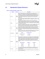
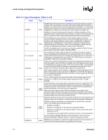
Land Listing and Signal Descriptions Table 4-3. Signal Description (Sheet 4 of 8) Name DRDY# Type Description Input/ Output DRDY# (Data Ready) is asserted by the data driver on each data transfer, indicating valid data on the data bus. In a multi-common clock data transfer, DRDY# may be de-asserted to insert idle clocks. This signal must connect the appropriate pins/lands of all processor FSB agents. DSTBN[3:0]# are the data strobes used to latch in D[63:0]#. DSTBN[3:0]# Input/ Output Signals D[15:0]#, DBI0# D[31:16]#, DBI1# D[47:32]#, DBI2# D[63:48]#, DBI3# Associated Strobe DSTBN0# DSTBN1# DSTBN2# DSTBN3# DSTBP[3:0]# DSTBP[3:0]# are the data strobes used to latch in D[63:0]#. Input/ Output Signals D[15:0]#, DBI0# D[31:16]#, DBI1# D[47:32]#, DBI2# D[63:48]#, DBI3# Associated Strobe DSTBP0# DSTBP1# DSTBP2# DSTBP3# FCx FERR#/PBE# GTLREF GTLREF_SEL HIT# HITM# IERR# Other FC signals are signals that are available for compatibility with other processors. Output FERR#/PBE# (floating point error/pending break event) is a multiplexed signal and its meaning is qualified by STPCLK#. When STPCLK# is not asserted, FERR#/PBE# indicates a floating-point error and will be asserted when the processor detects an unmasked floating-point error. When STPCLK# is not asserted, FERR#/PBE# is similar to the ERROR# signal on the Intel 387 coprocessor, and is included for compatibility with systems using MS-DOS*type floating-point error reporting. When STPCLK# is asserted, an assertion of FERR#/PBE# indicates that the processor has a pending break event waiting for service. The assertion of FERR#/PBE# indicates that the processor should be returned to the Normal state. For additional information on the pending break event functionality, including the identification of support of the feature and enable/disable information, refer to volume 3 of the Intel Architecture Software Developer's Manual and the Intel Processor Identification and the CPUID Instruction application note. Input GTLREF determines the signal reference level for GTL+ input signals. GTLREF is used by the GTL+ receivers to determine if a signal is a logical 0 or logical 1. Output GTLREF_SEL is used to select the appropriate chipset GTLREF voltage. Input/ Output Input/ Output HIT# (Snoop Hit) and HITM# (Hit Modified) convey transaction snoop operation results. Any FSB agent may assert both HIT# and HITM# together to indicate that it requires a snoop stall, which can be continued by reasserting HIT# and HITM# together. Output IERR# (Internal Error) is asserted by a processor as the result of an internal error. Assertion of IERR# is usually accompanied by a SHUTDOWN transaction on the processor FSB. This transaction may optionally be converted to an external error signal (e.g., NMI) by system core logic. The processor will keep IERR# asserted until the assertion of RESET#. This signal does not have on-die termination. Refer to Section 2.5 for termination requirements. Datasheet 69
-
 1
1 -
2
-
3
-
4
-
5
-
6
-
7
-
8
-
9
-
10
-
11
-
12
-
13
-
14
-
15
-
16
-
17
-
18
-
19
-
20
-
21
-
22
-
23
-
24
-
25
-
26
-
27
-
28
-
29
-
30
-
31
-
32
-
33
-
34
-
35
-
36
-
37
-
38
-
39
-
40
-
41
-
42
-
43
-
44
-
45
-
46
-
47
-
48
-
49
-
50
-
51
-
52
-
53
-
54
-
55
-
56
-
57
-
58
-
59
-
60
-
61
-
62
-
63
-
 64
64 -
 65
65 -
 66
66 -
 67
67 -
 68
68 -
 69
69 -
 70
70 -
 71
71 -
 72
72 -
 73
73 -
 74
74 -
75
-
76
-
77
-
78
-
79
-
80
-
81
-
82
-
83
-
84
-
85
-
86
-
87
-
88
-
89
-
90
-
91
-
92
-
93
-
94
-
95
-
96
 |
 |