Intel BLKD915GAV Product Specification - Page 37
Alert Standard Format ASF Support
 |
View all Intel BLKD915GAV manuals
Add to My Manuals
Save this manual to your list of manuals |
Page 37 highlights
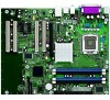
Product Description 1.11.2.2 RJ-45 LAN Connector with Integrated LEDs Two LEDs are built into the RJ-45 LAN connector (as shown in Figure 13). Table 9 describes the LED states when the board is powered up and the Gigabit LAN subsystem is operating. Green LED Green/Yellow LED OM16513 Figure 13. LAN Connector LED Locations Table 9. LAN Connector LED States LED Left Color Green LED State Off On Blinking N/A Off Right Green On Yellow On Condition LAN link is not established. LAN link is established. LAN activity is occurring. 10 Mbits/sec data rate is selected. 100 Mbits/sec data rate is selected. 1000 Mbits/sec data rate is selected. 1.11.3 Alert Standard Format (ASF) Support The boards provide the following ASF support for the onboard 10/100/1000 LAN subsystem, PCI Express x1 bus add-in LAN cards, and PCI Conventional bus add-in LAN cards installed in PCI Conventional bus slot 2: • Monitoring of system firmware progress events, including: ⎯ BIOS present ⎯ Primary processor initialization ⎯ Memory initialization ⎯ Video initialization ⎯ PCI resource configuration ⎯ Hard-disk initialization ⎯ User authentication ⎯ Starting operating system boot process • Monitoring of system firmware error events, including: ⎯ Memory missing ⎯ Memory failure ⎯ No video device ⎯ Keyboard failure ⎯ Hard-disk failure ⎯ No boot media • Boot options to boot from different types of boot devices • Reset, shutdown, power cycle, and power up options 37
-
 1
1 -
2
-
3
-
4
-
5
-
6
-
7
-
8
-
9
-
10
-
11
-
12
-
13
-
14
-
15
-
16
-
17
-
18
-
19
-
20
-
21
-
22
-
23
-
24
-
25
-
26
-
27
-
28
-
29
-
30
-
31
-
 32
32 -
 33
33 -
 34
34 -
 35
35 -
 36
36 -
 37
37 -
 38
38 -
 39
39 -
 40
40 -
 41
41 -
 42
42 -
43
-
44
-
45
-
46
-
47
-
48
-
49
-
50
-
51
-
52
-
53
-
54
-
55
-
56
-
57
-
58
-
59
-
60
-
61
-
62
-
63
-
64
-
65
-
66
-
67
-
68
-
69
-
70
-
71
-
72
-
73
-
74
-
75
-
76
-
77
-
78
-
79
-
80
-
81
-
82
-
83
-
84
-
85
-
86
-
87
-
88
-
89
-
90
-
91
-
92
-
93
-
94
-
95
-
96
-
97
-
98
-
99
-
100
-
101
-
102
-
103
-
104
-
105
-
106
 |
 |
