Intel BLKD945GCLF Product Specification - Page 45
Add-in Card Connectors, 2.2.3, Power Supply Connectors
 |
UPC - 735858201254
View all Intel BLKD945GCLF manuals
Add to My Manuals
Save this manual to your list of manuals |
Page 45 highlights
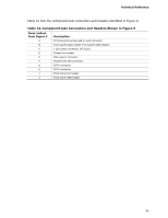
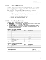
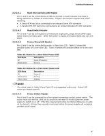
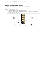
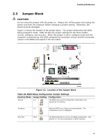
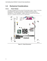
Technical Reference 2.2.2.2 Add-in Card Connectors The board has one PCI Conventional (rev 2.3 compliant) bus add-in card connector. PCI Conventional bus add-in cards with SMBus support can access sensor data and other information residing on the board. Note the following considerations for the PCI Conventional bus connectors: • The PCI Conventional bus connector is bus master capable. • SMBus signals are routed to the PCI Conventional bus connector. This enables PCI Conventional bus add-in boards with SMBus support to access sensor data on the board. The specific SMBus signals are as follows: ⎯ The SMBus clock line is connected to pin A40. ⎯ The SMBus data line is connected to pin A41. 2.2.2.3 Power Supply Connectors The board has the following power supply connectors: • Main power - a 2 x 10 connector. The board supports the use of ATX12V power supplies with 2 x 10 or 2 x 12 main power cables. • ATX12V power - a 2 x 2 connector. This connector provides power directly to the processor voltage regulator and must always be used. Failure to do so will prevent the board from booting. Table 15. Main Power Connector Pin 1 2 3 4 5 6 7 8 9 10 Signal Name +3.3 V +3.3 V Ground +5 V Ground +5 V Ground PWRGD (Power Good) +5 V (Standby) +12 V Pin 11 12 13 14 15 16 17 18 19 20 Signal Name +3.3 V -12 V Ground PS-ON# (power supply remote on/off) Ground Ground Ground +5 V +5 V +5 V Table 16. ATX12V Power Connector Pin Signal Name Pin 1 Ground 2 3 +12 V 4 Signal Name Ground +12 V For information about Power supply considerations Refer to Section 2.5.1, page 51 45
-
 1
1 -
2
-
3
-
4
-
5
-
6
-
7
-
8
-
9
-
10
-
11
-
12
-
13
-
14
-
15
-
16
-
17
-
18
-
19
-
20
-
21
-
22
-
23
-
24
-
25
-
26
-
27
-
28
-
29
-
30
-
31
-
32
-
33
-
34
-
35
-
36
-
37
-
38
-
39
-
 40
40 -
 41
41 -
 42
42 -
 43
43 -
 44
44 -
 45
45 -
 46
46 -
 47
47 -
 48
48 -
 49
49 -
 50
50 -
51
-
52
-
53
-
54
-
55
-
56
-
57
-
58
-
59
-
60
-
61
-
62
-
63
-
64
-
65
-
66
-
67
-
68
-
69
-
70
-
71
-
72
-
73
-
74
-
75
-
76
-
77
-
78
-
79
-
80
-
81
-
82
-
83
-
84
 |
 |
