Intel BLKD945GCNL Product Specification - Page 47
Table 14. Component-side Connectors and Headers Shown
 |
View all Intel BLKD945GCNL manuals
Add to My Manuals
Save this manual to your list of manuals |
Page 47 highlights
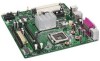
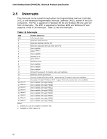
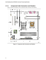
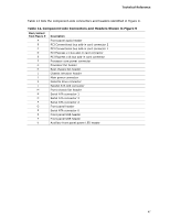
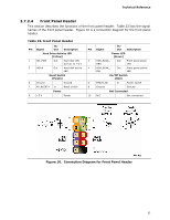
Technical Reference Table 14 lists the component-side connectors and headers identified in Figure 9. Table 14. Component-side Connectors and Headers Shown in Figure 9 Item/callout from Figure 9 Description A Front panel audio header B PCI Conventional bus add-in card connector 2 C PCI Conventional bus add-in card connector 1 D PCI Express x1 bus add-in card connector E PCI Express x16 bus add-in card connector F Processor core power connector G Processor fan header H Rear chassis fan header I Chassis intrusion header J Main power connector K Diskette drive connector L Parallel ATA IDE connector M Front chassis fan header N Serial ATA connector 1 O Serial ATA connector 3 P Serial ATA connector 2 Q Front panel header R Serial ATA connector 0 S Front panel USB header T Front panel USB header U Auxiliary front panel power LED header 47
-
 1
1 -
2
-
3
-
4
-
5
-
6
-
7
-
8
-
9
-
10
-
11
-
12
-
13
-
14
-
15
-
16
-
17
-
18
-
19
-
20
-
21
-
22
-
23
-
24
-
25
-
26
-
27
-
28
-
29
-
30
-
31
-
32
-
33
-
34
-
35
-
36
-
37
-
38
-
39
-
40
-
41
-
 42
42 -
 43
43 -
 44
44 -
 45
45 -
 46
46 -
 47
47 -
 48
48 -
 49
49 -
 50
50 -
 51
51 -
 52
52 -
53
-
54
-
55
-
56
-
57
-
58
-
59
-
60
-
61
-
62
-
63
-
64
-
65
-
66
-
67
-
68
-
69
-
70
-
71
-
72
-
73
-
74
-
75
-
76
-
77
-
78
-
79
-
80
-
81
-
82
-
83
-
84
-
85
-
86
-
87
-
88
-
89
-
90
 |
 |