Intel BLKDH61WWB3 Product Specification - Page 48
Front Panel Header
 |
View all Intel BLKDH61WWB3 manuals
Add to My Manuals
Save this manual to your list of manuals |
Page 48 highlights
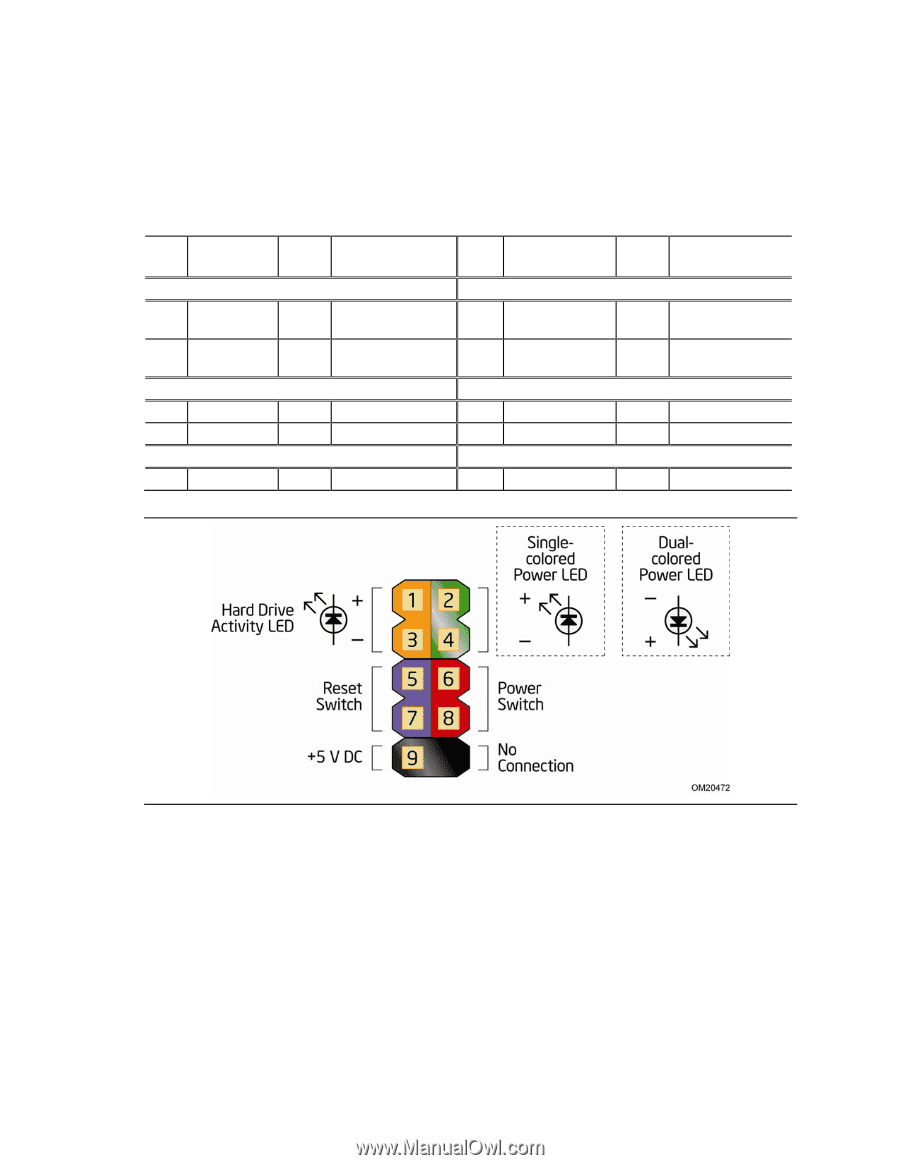
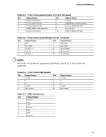
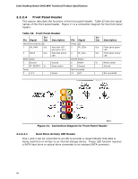
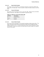
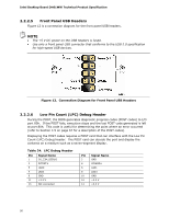
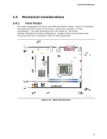
Intel Desktop Board DH61WW Technical Product Specification 2.2.2.4 Front Panel Header This section describes the functions of the front panel header. Table 22 lists the signal names of the front panel header. Figure 11 is a connection diagram for the front panel header. Table 22. Front Panel Header Pin Signal In/ Out Description Hard Drive Activity LED 1 HD_PWR Out Hard disk LED pull-up to +5 V 3 HDA# Out Hard disk active LED Reset Switch 5 Ground Ground 7 FP_RESET# In Reset switch Power 9 +5 V Power Pin Signal Power LED 2 FP_LED+ 4 FP_LED− On/Off Switch 6 PWR# 8 Ground Not Connected 10 N/C In/ Out Description Out Front panel green LED Out Front panel yellow LED In Power switch Ground Not connected Figure 11. Connection Diagram for Front Panel Header 2.2.2.4.1 Hard Drive Activity LED Header Pins 1 and 3 can be connected to an LED to provide a visual indicator that data is being read from or written to an internal storage device. Proper LED function requires a SATA hard drive or optical drive connected to an onboard SATA connector. 48
-
 1
1 -
2
-
3
-
4
-
5
-
6
-
7
-
8
-
9
-
10
-
11
-
12
-
13
-
14
-
15
-
16
-
17
-
18
-
19
-
20
-
21
-
22
-
23
-
24
-
25
-
26
-
27
-
28
-
29
-
30
-
31
-
32
-
33
-
34
-
35
-
36
-
37
-
38
-
39
-
40
-
41
-
42
-
 43
43 -
 44
44 -
 45
45 -
 46
46 -
 47
47 -
 48
48 -
 49
49 -
 50
50 -
 51
51 -
 52
52 -
 53
53 -
54
-
55
-
56
-
57
-
58
-
59
-
60
-
61
-
62
-
63
-
64
-
65
-
66
-
67
-
68
-
69
-
70
-
71
-
72
-
73
-
74
-
75
-
76
-
77
-
78
-
79
-
80
-
81
-
82
-
83
-
84
-
85
-
86
 |
 |