Contents
vii
Figures
1.
Intel Desktop Board D102GGC2 Components
..............................................................
11
2.
LAN Connector LEDs
....................................................................................................
16
3.
Location of the Standby Power Indicator
.......................................................................
20
4.
Installing the I/O Shield
.................................................................................................
25
5.
Desktop Board D102GGC2 Mounting Screw Hole Locations
........................................
26
6.
Lift Socket Lever
...........................................................................................................
27
7.
Lift the Load Plate and Don’t Touch the Socket Contacts
.............................................
27
8.
Remove the Protective Socket Cover
...........................................................................
28
9.
Remove the Processor from the Protective Processor Cover/Do Not Touch
.................
28
10. Install Processor
...........................................................................................................
29
11. Close the Load Plate
....................................................................................................
29
12. Connecting the Processor Fan Heat Sink Cable to the Processor Fan Connector
........
30
13. Use DDR DIMMs
..........................................................................................................
31
14. Installing a DIMM
..........................................................................................................
32
15. Installing a PCI Express x16 Card
................................................................................
34
16. Removing a PCI Express x16 Card
...............................................................................
35
17. Connecting the IDE Cable
............................................................................................
36
18. Connecting the Serial ATA Cable
.................................................................................
37
19. Internal Headers
...........................................................................................................
38
20. Back Panel Audio Connectors for a Flexible 6-Channel Audio System
.........................
41
21. Location of the Chassis Fan Headers
...........................................................................
42
22. Connecting 2 x 12 Power Supply Cables
......................................................................
43
23. Location of Other Connectors on Desktop Board D102GGC2
.......................................
44
24. Location of the BIOS Configuration Jumper Block
........................................................
45
25. Removing the Battery
...................................................................................................
51
Tables
1.
Feature Summary
...........................................................................................................
9
2.
Desktop Boards D102GGC2 Components
....................................................................
12
3.
Power Supply Requirements
.........................................................................................
13
4.
RJ-45 10/100 Ethernet LAN Connector LEDs
...............................................................
16
5.
Front Panel Audio Header Signal Names for High Definition Audio
...............................
39
6.
AC ’97 Audio Header Signal Names
.............................................................................
39
7.
Hi-Speed USB 2.0 Header Signal Names
.....................................................................
40
8.
Front Panel Header Signal Names
................................................................................
40
9.
Jumper Settings for the BIOS Setup Program Modes
...................................................
46
10.
Beep Codes
..................................................................................................................
55
11.
BIOS Error Messages
...................................................................................................
55
12.
Safety Regulations
........................................................................................................
57
13.
Lead-Free Board Markings
...........................................................................................
61
14.
EMC Regulations
..........................................................................................................
62
15.
Product Certification Markings
......................................................................................
63

 1
1 2
2 3
3 4
4 5
5 6
6 7
7 8
8 9
9 10
10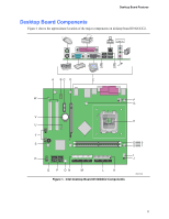 11
11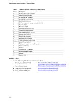 12
12