Intel D815EGEWLU Product Specification
Intel D815EGEWLU - P3 Socket 370 MicroATX Motherboard Manual
 |
UPC - 735858150590
View all Intel D815EGEWLU manuals
Add to My Manuals
Save this manual to your list of manuals |
Intel D815EGEWLU manual content summary:
- Intel D815EGEWLU | Product Specification - Page 1
October 2001 Order Number A73971-001 The Intel® Desktop Board D815EGEW may contain design defects or errors known as errata that may cause the product to deviate from published specifications. Current characterized errata are documented in the Intel Desktop Board D815EGEW Specification Update. - Intel D815EGEWLU | Product Specification - Page 2
may make changes to specifications and product descriptions at any time, without notice. The Intel® Desktop Board D815EGEW may contain design defects or errors known as errata that may cause the product to deviate from published specifications. Current characterized errata are available on - Intel D815EGEWLU | Product Specification - Page 3
and environmental requirements, and the BIOS for the Intel Desktop Boards D815EGEW. It describes the standard product and available A description of the hardware used on the D815EGEW board A map of the resources of the board The features supported by the BIOS Setup program The contents of - Intel D815EGEWLU | Product Specification - Page 4
Intel Desktop Board D815EGEW Technical Product Specification Other Common Notation # (NxnX) of a component, N indicates component type, xn are the relative coordinates of its location on the D815EGEW board, and X is the instance of the particular part at that general location. For example, J5J1 - Intel D815EGEWLU | Product Specification - Page 5
Support 16 1.4 Design Specifications 17 1.5 Processor ...19 1.6 System Memory ...20 1.7 Intel® 815EG Chipset 22 1.7.1 IDE Interfaces 23 1.7.2 USB...23 1.7.3 Real-Time Clock, CMOS SRAM, and Battery 24 1.8 I/O Controller ...24 1.8.1 Serial Port ...25 1.8.2 Parallel Port 25 1.8.3 Diskette Drive - Intel D815EGEWLU | Product Specification - Page 6
Intel Desktop Board D815EGEW Technical Product Specification 2.8 Connectors ...45 2.8.1 Back Support 79 3.6.2 Custom Splash Screen 79 3.7 Recovering BIOS Data 80 3.8 Boot Options...81 3.8.1 CD-ROM and Network Boot 81 3.8.2 Booting without Attached Devices 81 3.9 Fast Booting Systems with Intel - Intel D815EGEWLU | Product Specification - Page 7
Submenu 104 4.7.2 Hard Disk Drives Submenu 105 4.7.3 Removable Devices Submenu 105 4.7.4 ATAPI CDROM Drives Submenu 106 4.8 Exit Bus Initialization Checkpoints 113 5.4 Speaker ...114 5.5 BIOS Beep Codes ...115 Figures 1. Board Components...14 2. Block Diagram for the D815EGEW Board 15 3. Intel - Intel D815EGEWLU | Product Specification - Page 8
Intel Desktop Board D815EGEW Technical Product Specification Tables 1. Feature Summary...12 2. Manufacturing Options 13 3. Specifications ...17 4. Supported Processors 19 5. Supported Memory Configurations 21 6. Supported 53 35. PCI Bus Connectors 55 36. Diskette Drive Connector 56 37. IDE - Intel D815EGEWLU | Product Specification - Page 9
68 49. Thermal Considerations for Components 71 50. D815EGEW Board Environmental Specifications 72 51. Safety Regulations ...73 Boot Device Priority Submenu 104 73. Hard Disk Drives Submenu 105 74. Removeable Devices Submenu 105 75. ATAPI CDROM Drives Submenu 106 76. Exit Menu ...106 - Intel D815EGEWLU | Product Specification - Page 10
Intel Desktop Board D815EGEW Technical Product Specification x - Intel D815EGEWLU | Product Specification - Page 11
1 Product Description What This Chapter Contains 1.1 Overview ...12 1.2 Online Support ...16 1.3 Operating System Support 16 1.4 Design Specifications 17 1.5 Processor ...19 1.6 System Memory ...20 1.7 Intel® 815EG Chipset 22 1.8 I/O Controller ...24 1.9 Graphics Subsystem 26 1.10 Audio - Intel D815EGEWLU | Product Specification - Page 12
Product Specification 1.1 Overview 1.1.1 Feature Summary Table 1 summarizes the D815EGEW board's major features. Table 1. Feature Summary Form Factor Processor microATX (9.20 inches by 7.65 inches) Support for either an Intel® Pentium® III processor in a Flip Chip Pin Grid Array (FC-PGA - Intel D815EGEWLU | Product Specification - Page 13
D815EGEW board's manufacturing options. Not every manufacturing option is available in all marketing channels. Please contact your Intel still present at the DIMM and PCI bus connectors, even when the computer appears to be off Wake on LAN† Technology Connector Support for system wake up using an - Intel D815EGEWLU | Product Specification - Page 14
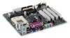
E Processor fan connector F BIOS Setup Configuration jumper G Intel 82815G GMCH H Processor socket I DIMM sockets J Power connector K Diskette drive connector connector (optional) U Intel 82801BA I/O Controller Hub (ICH2) V Intel 82802AB 4 Mbit Firmware Hub (FWH) W PCI bus add-in card connectors - Intel D815EGEWLU | Product Specification - Page 15
of the D815EGEW board. Primary/ Secondary IDE Processor Socket System Bus ATA-66/100 USB USB Ports (2) 815EG Chipset SDRAM Bus DIMM Banks (2) 82815G Graphics and Memory Controller Hub (GMCH) AHA Bus VGA Port Video Bus 82801BA I/O Controller Hub (ICH2) LPC Bus PCI Bus LPC I/O Controller - Intel D815EGEWLU | Product Specification - Page 16
... Intel's D815EGEW board under "Product Info" or "Customer Support" Processor data sheets ICH2 addressing Custom splash screens Audio software and utilities LAN software and drivers Visit this World Wide Web site: http://www.intel.com/design/motherbd http://support.intel.com/support/motherboards - Intel D815EGEWLU | Product Specification - Page 17
to the D815EGEW board. Services EPP IEEE Std 1284.1-1997 (Enhanced Parallel Port) El Torito Bootable CD-ROM Format Specification LPC MicroATX Low Pin Count Interface Specification microATX Motherboard Interface Specification Version, Revision Date, and Ownership Revision 2.1, May 1998, Intel - Intel D815EGEWLU | Product Specification - Page 18
Intel Desktop Board D815EGEW Technical Product Specification Table 3. Specifications (continued) Reference Name PCI Plug and Play SDRAM SMBIOS UHCI USB WfM Specification Title PCI Local Bus Specification PCI Bus Controller Interface Design Guide Universal Serial Bus Specification Wired for - Intel D815EGEWLU | Product Specification - Page 19
. See the Intel® Desktop D815EGEW Specification Update for the most up-to-date list of supported processors for the D815EGEW board. The D815EGEW board supports a single Pentium III or Celeron processor. The system bus frequency is automatically selected. The board supports the processors listed in - Intel D815EGEWLU | Product Specification - Page 20
Intel® SDRAM memory specifications, the board should be populated with DIMMs that support the impacted. The D815EGEW board has two DIMM sockets and supports the following memory 133 and 100 MHz) will default to 100 MHz. • 133 MHz SDRAM operation requires a 133 MHz system bus frequency processor - Intel D815EGEWLU | Product Specification - Page 21
Product Description Table 5 lists the supported DIMM configurations. Table 5. Supported Memory Configurations DIMM Capacity 32 MB 32 MB 48 MB 64 MB 64 MB 64 MB 96 MB 96 MB 128 MB 128 MB 128 - Intel D815EGEWLU | Product Specification - Page 22
Intel Desktop Board D815EGEW Technical Product Specification 1.7 Intel® 815EG Chipset The Intel® 815EG chipset consists of the following devices: • 82815G Graphics and Memory Controller Hub (GMCH) with Accelerated Hub Architecture (AHA) bus • 82801BA I/O Controller Hub (ICH2) with AHA bus • Intel - Intel D815EGEWLU | Product Specification - Page 23
DMA protocol on IDE bus allows host and target drive reports the transfer rate and translation mode to the BIOS. The D815EGEW board supports Laser Servo (LS-120) diskette technology through its IDE interfaces. The LS-120 drive drive) • ARMD-HDD (ATAPI removable media device - hard disk drive - Intel D815EGEWLU | Product Specification - Page 24
Intel Desktop Board D815EGEW Technical Product Specification ✏ NOTE Computer systems that have an unshielded cable ECP) and Enhanced Parallel Port (EPP) support • PS/2-style mouse and keyboard interfaces • Interface for one 1.2 MB, 1.44 MB, or 2.88 MB diskette drive • One fan control output The BIOS - Intel D815EGEWLU | Product Specification - Page 25
mode Refer to Figure 7, page 46 Table 22, page 48 Table 62, page 92 1.8.3 Diskette Drive Controller The I/O controller supports one diskette drive that is compatible with the 82077 diskette drive controller and supports both PC-AT and PS/2 modes. For information about The location of the diskette - Intel D815EGEWLU | Product Specification - Page 26
Intel Desktop Board D815EGEW Technical Product Specification The keyboard controller also supports the hot-key sequence for a software reset (operating system dependent). This key sequence resets the computer's software by jumping to the beginning - Intel D815EGEWLU | Product Specification - Page 27
Product Description Table 6 lists the refresh frequencies supported by the graphics subsystem. Table 6. Supported Graphics Refresh Frequencies Resolution 320 x 200 Color Palette 256 colors Available Refresh Frequencies (Hz) 70 Notes D 64 K colors 70 D3 16 M colors 70 D 320 x 240 - Intel D815EGEWLU | Product Specification - Page 28
Intel Desktop Board D815EGEW Technical Product Specification Table 6. Supported Graphics Refresh Frequencies (continued) and OpenGL† O = Overlay F = Digital Display Device only. A mode will be supported on both analog CRTs and digital display devices (KD3O applies to both types of displays), - Intel D815EGEWLU | Product Specification - Page 29
record/playback samples rates • Frequency response: 20 Hz to 20 kHz (± 0.1 dB) Figure 4 is a block diagram of the D815EGEW board's audio subsystem, including the Intel 82801BA ICH2 digital controller, the AD1885 analog codec, and the audio connectors. 82801BA I/O Controller Hub (ICH2) AC '97 Link - Intel D815EGEWLU | Product Specification - Page 30
Intel Desktop Board D815EGEW Technical Product Specification 1.10.2 Audio Connectors The audio connectors include the CD-ROM Connector A 1 x 4-pin ATAPI-style connector connects an internal ATAPI CD-ROM drive to the audio mixer. For information about The location of the ATAPI CD-ROM connector The - Intel D815EGEWLU | Product Specification - Page 31
Bus Master Interface • CSMA/CD Protocol Engine • Serial CSMA/CD unit interface that supports the 82562ET platform LAN connect device • PCI Power Management Supports ACPI technology Supports The Intel 82562ET provides the following functions: • Basic 10/100 Ethernet LAN Connectivity • Supports RJ - Intel D815EGEWLU | Product Specification - Page 32
Intel Desktop Board D815EGEW Technical Product support. ACPI features include: • Plug and Play (including bus and device enumeration) • Power management control of individual devices, add-in boards (some add-in boards may require an ACPI-aware driver), video displays, and hard disk drives - Intel D815EGEWLU | Product Specification - Page 33
information from applications and user settings to put the system as a whole into a low-power state. Table 9 lists the power states supported by the D815EGEW board along with the associated system power targets. See the ACPI specification for a complete description of the various system and power - Intel D815EGEWLU | Product Specification - Page 34
Intel Desktop Board D815EGEW or external source. No power to the system so that service can be performed. Notes: 1. Total system power is and 2) S1, S3 S1, S3 S1, S3 Notes: 1. S5 events are supported only on PCI bus connector 2. 2. For the Wake on LAN technology connector and PME#, S5 is disabled - Intel D815EGEWLU | Product Specification - Page 35
board devices that do not have other hardware standards for enumeration and configuration. PCI devices on the D815EGEW board, for example, are not enumerated by ACPI. 1.13.2 Hardware Support CAUTION If the Wake on LAN and Instantly Available technology features are used, ensure that the power - Intel D815EGEWLU | Product Specification - Page 36
Intel Desktop Board D815EGEW Technical Product Specification ✏ NOTE The use of Resume on Ring and Wake from USB technologies from an ACPI state requires an operating system that provides full ACPI support. 1.13.2.1 Power Connector When used with an ATX-compliant power supply that supports remote - Intel D815EGEWLU | Product Specification - Page 37
signal that powers up the computer. Depending on the LAN implementation, the D815EGEW board supports Wake on LAN technology in the following ways: • Through the Wake on LAN technology connector • Through the PCI bus PME# signal for PCI 2.2 compliant LAN designs (ACPI only) • Through the onboard - Intel D815EGEWLU | Product Specification - Page 38
Intel Desktop Board D815EGEW Technical Product Specification color.) When signaled by a wake-up device or event, the system quickly returns to its last known wake state. The D815EGEW board supports the PCI Bus Power Management Interface Specification. Add-in boards that also support this - Intel D815EGEWLU | Product Specification - Page 39
KB 64 KB 96 KB 160 KB 1 KB 127 KB 512 K Description Extended memory Runtime BIOS Reserved Available high DOS memory (open to the PCI bus) Video memory and BIOS Extended BIOS data (movable by memory manager software) Extended conventional memory Conventional memory 39 - Intel D815EGEWLU | Product Specification - Page 40
Intel Desktop Board D815EGEW Technical Product Specification 2.3 I/O Map Table 13. I/O Map Address (hex) 0000 - 000F 0020 Time Clock System CMOS DMA controller Fast A20 and PIC PIC DMA Numeric data processor Secondary IDE channel Primary IDE channel LPT3 LPT2 COM4/video (8514A) COM2 Secondary IDE - Intel D815EGEWLU | Product Specification - Page 41
TCO) 64 contiguous bytes starting on a 64-byte divisible boundary D815EGEW board resource 64 contiguous bytes starting on a 64-byte divisible boundary contiguous bytes starting on a 4096-byte divisible boundary ICH2 (SMBus) Intel 82801BA PCI bridge Note: Default, but can be changed to another - Intel D815EGEWLU | Product Specification - Page 42
Intel Desktop Board D815EGEW Technical Product Specification 2.4 DMA Channels Table 14. DMA Channels DMA Channel Number 0 1 2 3 4 5 6 7 Data Width 8 or 16 bits 8 or 16 bits 8 or 16 bits 8 or 16 bits 8 or 16 bits 16 bits 16 bits 16 bits System Resource Open Parallel port Diskette drive Parallel - Intel D815EGEWLU | Product Specification - Page 43
option) /User available 6 Diskette drive 7 LPT1 (Note) 8 Real-time clock 9 Reserved for ICH2 system management bus 10 User available 11 User available and how the interrupt signals are connected between the PCI bus connectors and onboard PCI devices. The PCI specification specifies - Intel D815EGEWLU | Product Specification - Page 44
Intel Desktop Board D815EGEW Technical Product Specification The ICH2 has eight programmable signals are routed on the D815EGEW board. For example, using Table 17 as a reference, assume that an add-in card using INTA is plugged into PCI bus connector 3. In PCI bus connector 3, INTA is connected - Intel D815EGEWLU | Product Specification - Page 45
CAUTION Only the back panel connectors of the D815EGEW board have overcurrent protection. The board's internal PCI bus connectors) IDE (two) Diskette drive • External I/O connectors (see page 58) SCSI LED (optional) Front panel (power/sleep/message waiting LED, power switch, hard drive - Intel D815EGEWLU | Product Specification - Page 46
Intel Desktop Board D815EGEW Technical Product Specification 2.8.1 Back Panel Connectors Figure 7 shows the location of the back panel connectors on the D815EGEW board. The back panel connectors are color-coded in compliance with PC 99 recommendations. The figure legend below lists the colors used. - Intel D815EGEWLU | Product Specification - Page 47
Poor audio quality occurs if passive (non-amplified) speakers are connected to this output. Table 18 lists the overcurrent protection for the D815EGEW board. Overcurrent protection is provided to the board's back panel connectors through thermistors. Table 18. Overcurrent Protection for Back Panel - Intel D815EGEWLU | Product Specification - Page 48
Intel Desktop Board D815EGEW Technical Product Specification Table 22. Parallel Port Connector Pin 1 2 3 4 5 6 7 8 9 10 11 12 13 14 15 16 17 18 - 25 Standard Signal Name STROBE# PD0 PD1 - Intel D815EGEWLU | Product Specification - Page 49
Table 24. LAN Connector (Optional) Pin Signal Name 1 TX+ 2 TX- 3 RX+ 4 Ground 5 Ground 6 RX- 7 Ground 8 Ground Table 25. Mic In Connector Pin Signal Name Tip Mono in Ring Mic bias voltage Sleeve Ground Table 26. Audio Line Out Connector Pin Signal Name Tip Audio left - Intel D815EGEWLU | Product Specification - Page 50
Intel Desktop Board D815EGEW Technical Product Specification 2.8.2 bus connector 2 (expansion slot 5). PCI add-in cards with SMBus support can access sensor data and other information residing on the desktop board. ✏ NOTE This document refers to back-panel slot numbering with respect to processor - Intel D815EGEWLU | Product Specification - Page 51
8 shows the location of the audio, power, and hardware control connectors on the D815EGEW boards. AB C 1 4 1 1 1 1 1 1 10 11 20 GFE Item A B C D E F G Description Auxiliary line in, ATAPI style ATAPI CD-ROM Processor fan (fan 1) Power Wake on LAN technology (optional) System fan (optional - Intel D815EGEWLU | Product Specification - Page 52
Intel Desktop Board D815EGEW Technical Product Specification Table 28. Auxiliary Line In audio differential ground 3 CD audio differential ground 4 Right audio input from CD-ROM Table 30. Processor Fan Connector Pin Signal Name 1 Ground 2 +12 V 3 No connect Table 31. Power Connector - Intel D815EGEWLU | Product Specification - Page 53
Technical Reference Table 32. Wake on LAN Technology Connector (Optional) Pin Signal Name 1 +5 V (standby) 2 Ground 3 WOL Table 33. System Fan Connector (Optional) Pin Signal Name 1 FAN2_PWM 2 +12 V 3 No connect Table 34. Chassis Intrusion Connector (Optional) Pin Signal Name 1 - Intel D815EGEWLU | Product Specification - Page 54
on the D815EGEW board. Note the following considerations for the PCI bus connectors: • All of the PCI bus connectors are bus master capable. • PCI bus connector 2 is S5 wake enabled. • PCI bus connector 2 has SMBus signals routed to it. This enables PCI bus add-in boards with SMBus support to access - Intel D815EGEWLU | Product Specification - Page 55
Notes: These signals (in parentheses) are optional in the PCI specification and are not currently implemented. ** On PCI bus connector 2, this pin is connected to the SMBus clock line. *** On PCI bus connector 2, this pin is connected to the SMBus data line. **** During S5 state, this pin is active - Intel D815EGEWLU | Product Specification - Page 56
Intel Desktop Board D815EGEW Technical Product Specification Table 36. Diskette Drive Connector Pin Signal Name 1 Ground 3 FDINDX# (Index) 10 FDM00# (Motor Enable A) 12 Not connected 14 FDDS0# (Drive Select A) 16 Not connected 18 FDDIR# (Stepper Motor Direction) 20 FDSTEP# (Step - Intel D815EGEWLU | Product Specification - Page 57
Activity LED Connector (Optional) The optional SCSI hard drive activity LED connector is a 1 x 3-pin connector that allows add-in SCSI host bus adapter to use the same LED as the IDE controller. This connector can be connected to the LED output of the add-in controller card. - Intel D815EGEWLU | Product Specification - Page 58
Intel Desktop Board D815EGEW Technical Product Specification 2.8.3 External I/O Connectors Figure 10 shows the locations of the external I/O connectors on the D815EGEW board. A 15 1 1 16 2 B Item A B Description Auxiliary front panel power LED Front panel For more information see: Table 39 - Intel D815EGEWLU | Product Specification - Page 59
Pins 5 and 7 can be connected to a momentary SPST type switch that is normally open. When the switch is closed, the D815EGEW board resets and runs the POST. 2.8.3.2.2 Hard Drive Activity LED Connector Pins 1 and 3 can be connected to an LED to provide a visual indicator that data is being read - Intel D815EGEWLU | Product Specification - Page 60
Intel Desktop Board D815EGEW Technical Product Specification Table 42. States for a Dual-Colored Power LED LED off. (The time requirement is due to internal debounce circuitry on the D815EGEW board.) At least two seconds must pass before the power supply will recognize another on/off signal. 60 - Intel D815EGEWLU | Product Specification - Page 61
cord from the computer before changing a jumper setting. Otherwise, the board could be damaged. Figure 11 shows the location of the jumper blocks on the D815EGEW board. 13 J2B1 13 J2B2 3 J6D1 1 Figure 11. Location of the Jumper Blocks OM12808 61 - Intel D815EGEWLU | Product Specification - Page 62
Intel Desktop Board D815EGEW Technical Product Specification 2.9.1 Wake from PS/2 Jumper Block This jumper block enables/disables Wake from PS/2 devices (PS/2 mouse and keyboard). Table 43 describes the - Intel D815EGEWLU | Product Specification - Page 63
Technical Reference 2.9.3 BIOS Setup Configuration Jumper Block This 3-pin jumper block determines the BIOS Setup program's mode. Table 45 describes the jumper settings for the three modes: normal, configure, and recovery. When the jumper is set to configure mode and the computer is powered-up, the - Intel D815EGEWLU | Product Specification - Page 64
Intel Desktop Board D815EGEW Technical Product Specification 2.10 Mechanical Considerations 2.10.1 Form Factor The D815EGEW board is designed to fit into a standard microATX-form-factor chassis. Figure 12 illustrates the mechanical form factor for the D815EGEW board. Dimensions are given in inches - Intel D815EGEWLU | Product Specification - Page 65
Shields The back panel I/O shield for the D815EGEW board must meet specific dimension and material requirements 16 Table 3, page 16 ✏ NOTE An I/O shield compliant with the ATX chassis specification 2.01 is available from Intel. 6.390 REF [162.30] 0.061 REF [1.55] 0.884 [22.45] 0.280 [7.10] 0.000 - Intel D815EGEWLU | Product Specification - Page 66
Intel Desktop Board D815EGEW Technical Product Specification 6.390 REF [162.30] 0.787 TYP [20.00] 6.268 0.005 [159.20 0.12] 2.071 [52 .65] 4.783 [121.50] 5.276 [134.00] 5.768 [146.501] Pictorial View Figure 14. I/O Shield Dimensions (for D815EGEW Boards with Onboard LAN Subsystem) OM12863 66 - Intel D815EGEWLU | Product Specification - Page 67
D815EGEW board and the following: • 1.20 GHz Intel Pentium III processor with a 256 KB cache and a 133 MHz system bus frequency • 256 MB SDRAM • 3.5-inch diskette drive • 4.3 GB ATA-33 IDE hard disk drive • IDE CD-ROM drive This information is provided only as a guide on S3 support configuration. - Intel D815EGEWLU | Product Specification - Page 68
draw for add-in boards in a fully-loaded D815EGEW board (all four expansion slots filled) must not exceed 8 A. 2.11.3 Standby Current Requirements CAUTION Power supplies used with the board must provide enough standby current to support the Instantly Available (ACPI S3 sleep state) configuration - Intel D815EGEWLU | Product Specification - Page 69
to a combined total of 700 mA. 2.11.4 Fan Connector Current Capability The D815EGEW board is designed to supply a maximum of 225 mA per fan connector. 2.11 total amount of standby current required depends on the wake devices supported and manufacturing options. Refer to Section 2.11.3 on page 68 - Intel D815EGEWLU | Product Specification - Page 70
regulator circuit. Figure 15 shows the locations of the localized high temperature zones for the D815EGEW board. A B C D OM12810 A Processor voltage regulator area B Processor C Intel 82815G Graphics and Memory Controller Hub (GMCH) D Intel 82801BA ICH2 Figure 15. Localized High Temperature Zones 70 - Intel D815EGEWLU | Product Specification - Page 71
to cool the D815EGEW board. Table 49. Thermal Considerations for Components Component Intel Pentium III processor Intel Celeron processor Intel 82815G GMCH Intel 82801BA ICH2 Maximum Case Temperature For processor case temperature, see processor datasheets and processor specification updates 116 - Intel D815EGEWLU | Product Specification - Page 72
Intel Desktop Board D815EGEW Technical Product Specification 2.14 Environmental Table 50 lists the environmental specifications for the D815EGEW boards. Table 50. D815EGEW Board Environmental Specifications Parameter Temperature Non-Operating Operating Shock Unpackaged Packaged Vibration - Intel D815EGEWLU | Product Specification - Page 73
of Nordic deviations to EN 60950. (Norway, Sweden, Denmark, and Finland) 2.15.2 EMC Regulations Table 52 lists the EMC regulations the D815EGEW board complies with when correctly installed in a compatible host system. Table 52. EMC Regulations Regulation FCC (Class B) ICES-003 (Class B) EN55022 - Intel D815EGEWLU | Product Specification - Page 74
boards: E210882 (component side). • FCC Declaration of Conformity logo mark for Class B equipment; to include Intel name and D815EGEW model designation (solder side). • CE mark: Declaring compliance to European Union (EU) EMC directive (89/336/EEC) and Low Voltage directive (73/23/EEC) (component - Intel D815EGEWLU | Product Specification - Page 75
Management BIOS (SMBIOS 77 3.5 Legacy USB Support 78 3.6 BIOS Updates ...79 3.7 Recovering BIOS Data 80 3.8 Boot Options...81 3.9 Fast Booting Systems with Intel® Rapid BIOS Boot 81 3.10 BIOS Security Features 83 3.1 Introduction The D815EGEW boards uses an Intel/AMI BIOS, which is stored in - Intel D815EGEWLU | Product Specification - Page 76
Intel Desktop Board D815EGEW Technical Product Specification 3.2 BIOS Flash Memory Organization The Firmware support. The IDE interface supports hard drives up to ATA-66/100 and recognizes any ATAPI devices, including CD-ROM drives, tape drives, and Ultra DMA drives (see Section 1.3 for the supported - Intel D815EGEWLU | Product Specification - Page 77
enables applications such as Intel® LANDesk® Client Manager to as memory size, cache size, and processor speed • Dynamic data, such as support, an SMBIOS service-level application running on a non-Plug and Play operating system can obtain the SMBIOS information. For information about The D815EGEW - Intel D815EGEWLU | Product Specification - Page 78
Intel Desktop Board D815EGEW Technical Product Specification 3.5 Legacy USB Support Legacy USB support enables USB devices such as keyboards, mice, and hubs to be used even when the operating system's USB drivers are not yet available. Legacy USB support is used to access the BIOS Setup program, and - Intel D815EGEWLU | Product Specification - Page 79
Web. • Intel® Flash Memory Update Utility, which requires creation of a boot diskette and manual rebooting of the system. Using this utility, the BIOS can be updated from a file on a 1.44 MB diskette (from a legacy diskette drive or an LS-120 diskette drive) or a CD-ROM. Both utilities support the - Intel D815EGEWLU | Product Specification - Page 80
Intel Desktop Board D815EGEW • Two beeps and the end of activity in the diskette drive indicate successful BIOS recovery. • A series of continuous beeps it. BIOS upgrades and the Intel Flash Memory Upgrade utility are available from Intel Customer Support through the Intel World Wide Web site. ✏ - Intel D815EGEWLU | Product Specification - Page 81
drive to be the first boot device, the hard drive second, and the ATAPI CD-ROM third. The fourth device is disabled. 3.8.1 CD-ROM and Network Boot Booting from CD-ROM is supported peripherals properly • Using an optimized BIOS, such as the Intel® Rapid BIOS The BIOS is not configured by default to - Intel D815EGEWLU | Product Specification - Page 82
Intel Desktop Board D815EGEW Technical Product Specification 3.9.1 Peripheral Selection and Configuration The following techniques will help speed system boot: • Choose a hard drive with parameters such as "power-up to data ready" less than eight seconds to minimize hard drive startup delays. The - Intel D815EGEWLU | Product Specification - Page 83
Overview of BIOS Features 3.10 BIOS Security Features The BIOS includes security features that restrict access to the BIOS Setup program and who can boot the computer. A supervisor password and a user password can be set for the BIOS Setup program and for booting the computer, with the following - Intel D815EGEWLU | Product Specification - Page 84
Intel Desktop Board D815EGEW Technical Product Specification 84 - Intel D815EGEWLU | Product Specification - Page 85
4 BIOS Setup Program What This Chapter Contains 4.1 Introduction...85 4.2 Maintenance Menu ...86 4.3 Main Menu...88 4.4 Advanced Menu...89 4.5 Security Menu ...100 4.6 Power Menu ...101 4.7 Boot Menu ...103 4.8 Exit Menu ...106 4.1 Introduction The BIOS Setup program can be used to view and - Intel D815EGEWLU | Product Specification - Page 86
Intel Desktop Board D815EGEW Technical Product Specification Table 55 lists the function keys available for menu the user and administrative passwords. Clears the Wired for Management Boot Integrity Service (BIS) credentials. Invokes the Extended Configuration submenu. Displays CPU's Microcode - Intel D815EGEWLU | Product Specification - Page 87
cache mode. This setting identifies the video memory range as uncacheable by the processor. Memory writes are performed in program order. Cache lookups are not performed. Well suited for applications not supporting Write Combining. Sets extended memory configuration options to Auto or User Defined - Intel D815EGEWLU | Product Specification - Page 88
Intel Desktop Board D815EGEW Technical Product Specification 4.3 Main Menu To access this menu, select Main on the menu bar at the top of the screen. Maintenance Main Advanced Security Power Boot Exit Table 58 describes the Main Menu. This menu reports processor and memory information and is - Intel D815EGEWLU | Product Specification - Page 89
BIOS Setup Program 4.4 Advanced Menu To access this menu, select Advanced on the menu bar at the top of the screen. Maintenance Main Advanced Security Power PCI Configuration Boot Configuration Peripheral Configuration IDE Configuration Diskette Configuration Event Log Configuration Video - Intel D815EGEWLU | Product Specification - Page 90
Intel Desktop Board D815EGEW Technical Product Specification 4.4.1 PCI Configuration Submenu To access this submenu, select Advanced on the menu bar, then PCI Configuration. Maintenance Main Advanced Security Power PCI - Intel D815EGEWLU | Product Specification - Page 91
Feature Plug & Play O/S Reset Config Data Numlock Options • No (default) • Yes • No (default) • Yes • Off • On (default) Description Specifies if manual configuration is desired. No lets the BIOS configure all devices. This setting is appropriate when using a Plug and Play operating system. Yes - Intel D815EGEWLU | Product Specification - Page 92
Intel Desktop Board D815EGEW Technical Product Specification 4.4.3 Peripheral Configuration Submenu To access this submenu, select Advanced on the menu bar, then Peripheral Configuration. Maintenance Main Advanced Security Power PCI - Intel D815EGEWLU | Product Specification - Page 93
set to Enabled) DMA Channel (This feature is present only when Parallel Port Mode is set to ECP) Audio Device Legacy USB Support Options • 378 (default) • 278 Description Specifies the base I/O address for the parallel port. • IRQ 5 • IRQ 7 (default) • 1 • 3 (default) Specifies the interrupt for - Intel D815EGEWLU | Product Specification - Page 94
Intel Desktop Board D815EGEW Technical Product Specification 4.4.4 IDE Configuration Submenu To access this submenu . Both enables both IDE controllers. Enables or disables PCI IDE bus master capability. Specifies the hard disk drive pre-delay. Reports type of connected IDE device. When selected, - Intel D815EGEWLU | Product Specification - Page 95
changed. Auto fills-in capabilities from ATA/ATAPI device. Displays the capacity of the drive. Enables or disables LBA mode control. Specifies number of sectors per block for transfers from the hard disk drive to memory. Check the hard disk drive's specifications for optimum setting. continued 95 - Intel D815EGEWLU | Product Specification - Page 96
Intel Desktop Board D815EGEW Technical Product Specification Table 64. Primary/Secondary IDE Master/Slave Submenus (continued) Mode 5 None Description Specifies the PIO mode. Specifies the Ultra DMA mode for the drive. Displays the type of cable connected to the IDE interface: 40-conductor or 80- - Intel D815EGEWLU | Product Specification - Page 97
Event Log Configuration Video Configuration Boot Exit The submenu represented by Table 65 is used for configuring the diskette drive. Table 65. Diskette Configuration Submenu Feature Diskette Controller Floppy A Diskette Write Protect Options • Disabled • Enabled (default) • Not Installed - Intel D815EGEWLU | Product Specification - Page 98
Intel Desktop Board D815EGEW Technical Product Specification 4.4.6 Event Log Configuration Submenu To access this menu, select Advanced on the menu bar, then Event Log Configuration. Maintenance Main Advanced Security - Intel D815EGEWLU | Product Specification - Page 99
BIOS Setup Program 4.4.7 Video Configuration Submenu To access this menu, select Advanced on the menu bar, then Video Configuration. Maintenance Main Advanced Security Power PCI Configuration Boot Configuration Peripheral Configuration IDE Configuration Diskette Configuration Event Log - Intel D815EGEWLU | Product Specification - Page 100
Intel Desktop Board D815EGEW Technical Product Specification 4.5 Security Menu To access this 2. This feature appears only if a supervisor password has been set. 3. If both Legacy USB Support (in the Peripheral Configuration submenu) and Unattended Start (in the Security menu) are enabled, USB - Intel D815EGEWLU | Product Specification - Page 101
BIOS Setup Program 4.6 Power Menu To access this menu, select Power from the menu bar at the top of the screen. Maintenance Main Advanced Security Power Boot Exit The menu represented in Table 69 is for setting the power management features. Table 69. Power Menu Feature Options Description - Intel D815EGEWLU | Product Specification - Page 102
Intel Desktop Board D815EGEW Technical Product Specification 4.6.1 ACPI Submenu To access this menu, select Power on the menu bar, then ACPI. Maintenance Main Advanced Security Power ACPI Boot Exit - Intel D815EGEWLU | Product Specification - Page 103
boot features and the boot sequence. Table 71. Boot Menu Feature Quiet Boot Intel Rapid BIOS Boot Scan User Flash Area Boot Device Priority Hard Disk Drives Removable Devices ATAPI CD-ROM Drives Options Description • Disabled Disabled displays normal POST messages. • Enabled (default) Enabled - Intel D815EGEWLU | Product Specification - Page 104
device types (removable devices, hard drives, and ATAPI CD-ROM drives), the entries in this list will reflect as many boot entry vector (BEV) boot devices (for example, Intel UNDI, PXE devices) and SCSI CD-ROM drives as are installed, up to the five BEV boot devices supported by the BIOS. 2. While - Intel D815EGEWLU | Product Specification - Page 105
submenu appears only if at least one boot device of this type is installed. This list will display up to twelve hard disk drives, the maximum number of hard disk drives supported by the BIOS. 4.7.3 Removable Devices Submenu To access this menu, select Boot on the menu bar, then Removable Devices - Intel D815EGEWLU | Product Specification - Page 106
Intel Desktop Board D815EGEW Technical Product Specification 4.7.4 ATAPI CDROM Drives Submenu To access this menu, select Boot on the menu bar, then ATAPI CDROM Drives. Maintenance Main Advanced Security Power Boot Exit Boot Device Priority Hard Disk Drives Removeable Devices ATAPI CDROM - Intel D815EGEWLU | Product Specification - Page 107
Chapter Contains 5.1 BIOS Error Messages 107 5.2 Port 80h POST Codes 109 5.3 Bus Initialization Checkpoints 113 5.4 Speaker ...114 5.5 BIOS Beep Codes ...115 5.1 BIOS Error occurred trying to access diskette drive controller. Error occurred trying to access hard disk controller. continued 107 - Intel D815EGEWLU | Product Specification - Page 108
Intel Desktop Board D815EGEW Technical Product Specification Table 77. BIOS Error Messages (continued) Memory size has increased since the last boot. If no memory was added there may be a problem with the system. Memory Size Changed Memory size has changed since the last boot. If no memory - Intel D815EGEWLU | Product Specification - Page 109
in F000 Shadow RAM. Initialize interrupt vector tables, initialize system timer, initialize DMA controller and interrupt controller. Initialize extra (Intel Recovery) Module. Initialize floppy drive. Try to boot from floppy. If reading of boot sector is successful, give control to boot sector code - Intel D815EGEWLU | Product Specification - Page 110
Intel Desktop Board D815EGEW Technical Product Specification Table 80. Runtime Code Uncompressed in F000 Shadow RAM Code 03 05 06 07 08 0B 0C 0E 0F 10 11 12 - Intel D815EGEWLU | Product Specification - Page 111
Error Messages and Beep Codes Table 80. Runtime Code Uncompressed in F000 Shadow RAM (continued) Code 40 42 43 44 45 46 47 48 49 4B 4C 4D 4E 4F 50 51 52 53 54 57 58 59 60 62 65 66 7F 80 81 82 83 Description of POST Operation To prepare the descriptor tables. To enter in virtual mode for memory - Intel D815EGEWLU | Product Specification - Page 112
Intel Desktop Board D815EGEW Technical start. Going for hard disk controller reset. Hard disk controller reset done. Floppy setup to be done next. Floppy setup complete. Hard disk setup to be shadow. Generate MP for multiprocessor support (if present). Put CGA INT10 module (if present) in - Intel D815EGEWLU | Product Specification - Page 113
execution. In these WORD checkpoints, the low byte of the checkpoint is the system BIOS checkpoint from which the control is passed to the different bus routines. The high byte of the checkpoint is the indication of which routine is being executed in the different buses. Table 82 describes the upper - Intel D815EGEWLU | Product Specification - Page 114
Intel Desktop Board D815EGEW Technical Product Specification Table 83 describes the lower nibble of the high byte and indicates the bus on which the routines are being executed. Table 83. Lower Nibble High Byte Functions Value Description 0 Generic DIM (Device Initialization Manager) 1 - Intel D815EGEWLU | Product Specification - Page 115
Error Messages and Beep Codes 5.5 BIOS Beep Codes Whenever a recoverable error occurs during POST, the BIOS displays an error message describing the problem (see Table 84). The BIOS also issues a beep code (one long tone followed by two short tones) during POST if the video configuration fails (a - Intel D815EGEWLU | Product Specification - Page 116
-
 1
1 -
 2
2 -
 3
3 -
 4
4 -
 5
5 -
 6
6 -
 7
7 -
8
-
9
-
10
-
11
-
12
-
13
-
14
-
15
-
16
-
17
-
18
-
19
-
20
-
21
-
22
-
23
-
24
-
25
-
26
-
27
-
28
-
29
-
30
-
31
-
32
-
33
-
34
-
35
-
36
-
37
-
38
-
39
-
40
-
41
-
42
-
43
-
44
-
45
-
46
-
47
-
48
-
49
-
50
-
51
-
52
-
53
-
54
-
55
-
56
-
57
-
58
-
59
-
60
-
61
-
62
-
63
-
64
-
65
-
66
-
67
-
68
-
69
-
70
-
71
-
72
-
73
-
74
-
75
-
76
-
77
-
78
-
79
-
80
-
81
-
82
-
83
-
84
-
85
-
86
-
87
-
88
-
89
-
90
-
91
-
92
-
93
-
94
-
95
-
96
-
97
-
98
-
99
-
100
-
101
-
102
-
103
-
104
-
105
-
106
-
107
-
108
-
109
-
110
-
111
-
112
-
113
-
114
-
115
-
116
 |
 |

Intel
®
Desktop Board
D815EGEW
Technical Product Specification
October 2001
Order Number
A73971-001
The Intel
®
Desktop Board D815EGEW may contain design defects or errors known as errata that may cause the product to deviate from published specifications.
Current
characterized errata are documented in the Intel Desktop Board D815EGEW Specification Update.