Intel D845PEMY Product Specification
Intel D845PEMY Manual
 |
View all Intel D845PEMY manuals
Add to My Manuals
Save this manual to your list of manuals |
Intel D845PEMY manual content summary:
- Intel D845PEMY | Product Specification - Page 1
August 2004 Order Number: C83645-001 The Intel® Desktop Board D845PEMY may contain design defects or errors known as errata that may cause the product to deviate from published specifications. Current characterized errata are documented in the Intel Desktop Board D845PEMY Specification Update. - Intel D845PEMY | Product Specification - Page 2
Date August 2004 This product specification applies to only standard Intel® Desktop Board D845PEMY with BIOS identifier FN84510A.86A. Changes to this specification will be published in the Intel Desktop Board D845PEMY Specification Update before being incorporated into a revision of this document - Intel D845PEMY | Product Specification - Page 3
Contains Chapter 1 2 3 4 Description A description of the hardware used on the Desktop Board D845PEMY A map of the resources of the Desktop Board The features supported by the BIOS Setup program A description of the BIOS error messages, beep codes, and POST codes Typographical Conventions This - Intel D845PEMY | Product Specification - Page 4
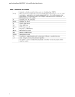
Intel Desktop Board D845PEMY Technical Product Specification Other Common Notation # (NxnX) GB component, N indicates component type, xn are the relative coordinates of its location on the Desktop Board D845PEMY, and X is the instance of the particular part at that general location. For example, - Intel D845PEMY | Product Specification - Page 5
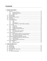
1.1 Overview ...10 1.1.1 Feature Summary 10 1.1.2 Manufacturing Options 11 1.1.3 Board Layout 12 1.2 Block Diagram...13 1.3 Online Support ...14 1.4 Operating System Support 14 1.5 Processor ...15 1.6 System Memory ...16 1.7 Intel® 845PE Chipset 18 1.7.1 AGP ...18 1.7.2 USB ...19 1.7.3 IDE - Intel D845PEMY | Product Specification - Page 6
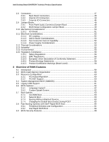
Intel Desktop Board D845PEMY Technical Product Specification 2.8 Connectors...37 2.8.1 Back Panel Connectors 38 2.8.2 Internal I/O Connectors 39 2.8.3 External I/O Connectors 44 2.9 Jumper Blocks...48 2.9.1 Front Panel Audio Connector/Jumper Block 48 2.9.2 BIOS Setup Configuration Jumper Block - Intel D845PEMY | Product Specification - Page 7
Initialization Checkpoints 73 4.4 Speaker ...74 4.5 BIOS Beep Codes...74 Figures 1. Desktop Board D845PEMY Components 12 2. Block Diagram...13 3. Location of the Standby Power Indicator LED on the D845PEMY Board 30 4. Back Panel Connectors 38 5. Audio, Power, and Hardware Control Connectors 40 - Intel D845PEMY | Product Specification - Page 8
Intel Desktop Board D845PEMY Technical Product Specification 26. States for a One-Color Power LED 46 27. States for a Two-Color Power LED 46 28. Front Panel Audio Connector/Jumper Block 49 29. BIOS Setup Configuration Jumper Settings 49 30. DC Loading Characteristics 52 31. Fan Connector - Intel D845PEMY | Product Specification - Page 9
1.1 Overview ...10 1.2 Block Diagram...13 1.3 Online Support ...14 1.4 Operating System Support 14 1.5 Processor ...15 1.6 System Memory ...16 1.7 Intel® 845PE Chipset 18 1.8 I/O Controller...21 1.9 Audio Subsystem ...22 1.10 LAN Subsystem ...23 1.11 Hardware Management Subsystem (Optional 24 - Intel D845PEMY | Product Specification - Page 10
Feature Summary Table 1 summarizes the major features of the Intel® Desktop Board D845PEMY. Table 1. Feature Summary Form Factor Processor microATX (9.20 inches by 8.20 inches [233.68 millimeters by 208.28 millimeters]) • Support for an Intel® Pentium® 4 processor in an mPGA478 socket with a 400 - Intel D845PEMY | Product Specification - Page 11
Description 1.1.2 Manufacturing Options Table 2 describes the manufacturing options on the Desktop Board D845PEMY. Not every manufacturing option is available in all marketing channels. Please contact your Intel representative to determine which manufacturing options are available to you. Table - Intel D845PEMY | Product Specification - Page 12
intrusion connector BIOS Setup configuration jumper block 3 Mbit Firmware Hub (FWH) Front panel connector Front panel USB connector Intel 82801DB I/O Controller Hub (ICH4) AGP connector PCI bus add-in card connectors Front panel audio connector Figure 1. Desktop Board D845PEMY Components 12 - Intel D845PEMY | Product Specification - Page 13
a block diagram of the major functional areas of the board. = connector or socket Primary/ Secondary IDE UDMA 33 Intel 82801DB I/O Controller Hub (ICH4) 3 Mbit Firmware Hub (FWH) Intel 845PE Chipset CSMA/CD Unit Interface AC Link Physical Layer Interface LAN Connector Realtek ALC202A Audio - Intel D845PEMY | Product Specification - Page 14
for the Desktop Board D845PEMY Processor data sheets ICH4 addressing Custom splash screens Audio software and utilities LAN software and drivers Visit this World Wide Web site: http://www.intel.com/design/motherbd http://support.intel.com/support/motherboards/desktop http://developer.intel.com - Intel D845PEMY | Product Specification - Page 15
Intel web site listed below for the most up-to-date list of supported processors. For information about... Supported processors for the D845PEMY board Refer to: http://www.intel SFX12V-, or TFX12V-compliant power supplies with the Desktop Board D845PEMY. ATX12V, SFX12V, and TFX12V power supplies - Intel D845PEMY | Product Specification - Page 16
Intel Desktop Board D845PEMY Technical Product Specification 1.6 System Memory The Desktop Board D845PEMY has two DIMM sockets and is designed to support up to 2 GB of single-channel DDR SDRAM memory. The board supports the following memory features: • 2.5 V (only) 184-pin DDR SDRAM DIMMs with gold - Intel D845PEMY | Product Specification - Page 17
Product Description Table 4 lists the supported DDR DIMM configurations. Table 4. Supported DDR DIMM Configurations DIMM Capacity Configuration DDR SDRAM (Note) Density DDR SDRAM Organization Number of DDR Front-side/Back-side SDRAM Devices 64 MB SS - Intel D845PEMY | Product Specification - Page 18
Intel Desktop Board D845PEMY Technical Product Specification 1.7 Intel® 845PE Chipset The Intel 845PE chipset consists of the following devices: • Intel 82845PE Memory Controller Hub (MCH) with Accelerated Hub Architecture (AHA) bus • Intel 82801DB I/O Controller Hub (ICH4) with AHA bus • Firmware - Intel D845PEMY | Product Specification - Page 19
Product Description 1.7.2 USB The board supports up to four USB 2.0 ports, fully supports UHCI and EHCI, and uses UHCI- and EHCI-compatible drivers. For more than four USB devices, an external hub can be connected to any of the ports. The ICH4 provides the USB controller for all - Intel D845PEMY | Product Specification - Page 20
Intel Desktop Board D845PEMY Technical Product Specification # INTEGRATOR'S NOTE ATA-66 and ATA-100 are faster timings and require a specialized cable to reduce reflections, noise, and inductive coupling. The IDE interfaces also support ATAPI devices (such as CD-ROM drives) and ATA devices. The BIOS - Intel D845PEMY | Product Specification - Page 21
back panel. Serial port B (optional) is accessible using a connector on the component side of the Desktop Board. The serial ports support data transfers at speeds up to 115.2 kbits/sec with BIOS support. For information about The location of the serial port A connector The location of the optional - Intel D845PEMY | Product Specification - Page 22
Intel Desktop Board D845PEMY Technical Product Specification 1.9 Audio Subsystem The audio subsystem consists of the following devices: • Intel 82801DB I/O Controller Hub (ICH4) • Realtek ALC202A audio codec The audio subsystem includes these features: • Signal-to-noise ratio ≥ 90 dB • Supports - Intel D845PEMY | Product Specification - Page 23
• Full device driver compatibility • ACPI support • Programmable transit threshold • Configuration EEPROM that contains the MAC address 1.10.2 RJ-45 LAN Connector with Integrated LEDs Two LEDs are built into the RJ-45 LAN connector. Table 5 describes the LED states when the Desktop Board is powered - Intel D845PEMY | Product Specification - Page 24
Intel Desktop Board D845PEMY Technical Product Specification 1.11 Hardware Management Subsystem (Optional) The hardware management features enable the boards to be compatible with the Wired for Management (WfM) specification. The board Intrusion and Detection The board supports a chassis security - Intel D845PEMY | Product Specification - Page 25
an operating system that provides full ACPI support. ACPI features include: • Plug and Play (including bus and device enumeration) • Power management control of individual devices, add-in boards (some add-in boards may require an ACPI-aware driver), video displays, and hard disk drives • Methods for - Intel D845PEMY | Product Specification - Page 26
Intel Desktop Board D845PEMY states supported by the Desktop Board D845PEMY along with Processor stopped S3 - Suspend to RAM. Context saved to RAM. S4 - Suspend to disk. Service can be performed safely. Notes: 1. Total system power is dependent on the system configuration, including add-in boards - Intel D845PEMY | Product Specification - Page 27
of standby current required depends on the wake devices supported and manufacturing options. The Desktop Board D845PEMY provides several power management hardware features, including: • Power connector • Fan connectors • LAN wake capabilities • Instantly Available PC technology • Resume on Ring - Intel D845PEMY | Product Specification - Page 28
Intel Desktop Board D845PEMY ACPI state requires an operating system that provides full ACPI support. 1.12.2.1 Power Connector ATX12V-, SFX12V-, and TFX12V-compliant can be set using the Last Power State feature in the BIOS Setup program's Boot menu. For information about The location of the - Intel D845PEMY | Product Specification - Page 29
frame, the LAN subsystem asserts a wake-up signal that powers up the computer. Depending on the LAN implementation, the board supports LAN wake capabilities with power supply. Instantly Available PC technology enables the board to enter the ACPI S3 (Suspend-to-RAM) sleep-state. While in the S3 sleep- - Intel D845PEMY | Product Specification - Page 30
Intel Desktop Board D845PEMY Technical Product Specification CR1F1 OM17287 Figure 3. Location of the Standby Power Indicator LED on the D845PEMY Board the use of a USB peripheral that supports Wake from USB. 1.12.2.8 Wake from state. 1.12.2.9 PME# Signal Wake-up Support When the PME# signal on the PCI - Intel D845PEMY | Product Specification - Page 31
- 7FFFF Size 2047 MB 64 KB 64 KB 96 KB 160 KB 1 KB 127 KB 512 KB Description Extended memory Runtime BIOS Reserved Available high DOS memory (open to the PCI bus) Video memory and BIOS Extended BIOS data (movable by memory manager software) Extended conventional memory Conventional memory 31 - Intel D845PEMY | Product Specification - Page 32
Intel Desktop Board D845PEMY Technical Product Specification 2.3 Fixed I/O Map Table 11. I/O Map Address (hex bytes 4 bytes 1 byte 4 bytes 8 bytes 8 bytes Description Used by the Desktop Board D845PEMY. Refer to the ICH4 data sheet for dynamic addressing information. Secondary IDE channel Primary - Intel D845PEMY | Product Specification - Page 33
P2P) Hub link to PCI bridge Intel 82801DB ICH4 PCI to LPC bridge IDE controller SMBus controller AC '97 audio controller AC '97 modem controller (optional) USB UHCI controller 1 USB UHCI controller 2 USB UHCI controller 3 EHCI controller AGP add-in card LAN controller PCI bus connector 1 PCI bus - Intel D845PEMY | Product Specification - Page 34
Intel Desktop Board D845PEMY Technical Product Specification 2.6 Interrupts The interrupts can be routed through either the Programmable Interrupt Controller (PIC) or the Advanced Programmable Interrupt Controller (APIC) portion of the ICH4 component. The PIC is supported in Windows 98 SE and - Intel D845PEMY | Product Specification - Page 35
either onboard or from a PCI add-in card connect to one of these PIRQ signals. Some PCI interrupt sources are electrically tied together on the Desktop Board D845PEMY and therefore share the same interrupt. Table 15 shows an example of how the PIRQ signals are routed. For example, using Table 15 as - Intel D845PEMY | Product Specification - Page 36
Intel Desktop Board D845PEMY Technical Product Specification Table 15. PCI Interrupt Routing Map PCI Interrupt Source PIRQA AGP connector INTA ICH4 USB UHCI controller 1 INTA SMBus controller ICH4 USB UHCI controller 2 AC '97 ICH4 Audio/Modem ICH4 LAN ICH4 USB UHCI controller 3 ICH4 USB - Intel D845PEMY | Product Specification - Page 37
USB, front panel USB, VGA, and PS/2 connectors have overcurrent protection. The Desktop Boards' internal connectors are not overcurrent Serial port A ⎯ LAN ⎯ Audio (line out, line in, and mic in) • Internal I/O connectors (see page 39) ⎯ Front panel audio ⎯ Fans ⎯ Power ⎯ Add-in boards (PCI) ⎯ IDE ⎯ - Intel D845PEMY | Product Specification - Page 38
Intel Desktop Board D845PEMY Technical Product Specification 2.8.1 Back Panel Connectors Figure mouse port B PS/2 keyboard port C Serial port A D Parallel port E LAN F USB ports G Audio line in H Mic in I Audio line out Color Green Purple Teal Burgundy Black Black Light blue Pink Lime green - Intel D845PEMY | Product Specification - Page 39
, and hardware control (see page 40) ⎯ Front panel audio ⎯ Fans (3) ⎯ ATX12V power ⎯ Main power ⎯ Chassis intrusion • Add-in boards and peripheral interfaces (see page 43) ⎯ PCI bus ⎯ IDE ⎯ Diskette drive 2.8.2.1 Expansion Slots The Desktop Board has three PCI rev 2.2 compliant local bus slots. The - Intel D845PEMY | Product Specification - Page 40
Intel Desktop Board D845PEMY Technical Product Specification 2.8.2.2 Audio, Power, and Hardware Control Connectors Figure 5 shows the location of the audio, power, and hardware control connectors. A B 12 9 10 12 34 3 C 1 1 3 D 11 3 20 11 10 1 GF Item A B C D E F G Description Front - Intel D845PEMY | Product Specification - Page 41
4-pin leads of ATX12V, SFX12V, and TFX12V power supplies to the corresponding connectors on the Desktop Board, otherwise the Desktop Board will not boot. • Do not use a standard ATX power supply. The Desktop Board will not boot with a standard ATX power supply. Table 17. ATX12V Power Connector Pin - Intel D845PEMY | Product Specification - Page 42
Intel Desktop Board D845PEMY Technical Product Specification Table 20. Main Power Connector Pin Signal Name Pin 1 +3.3 V 11 2 +3.3 V 12 3 Ground 13 4 +5 V 14 5 Ground 15 6 +5 V 16 7 Ground 17 8 PWRGD (Power Good) - Intel D845PEMY | Product Specification - Page 43
for the Desktop Board D845PEMY. Note the following considerations for the PCI bus connectors: • All of the PCI bus connectors are bus master capable. • SMBus signals are routed to PCI bus connector 2, enabling PCI bus add-in boards with SMBus support to access sensor data on the Desktop Board. The - Intel D845PEMY | Product Specification - Page 44
Intel Desktop Board D845PEMY Technical Product Specification 2.8.3 External I/O Connectors Figure 7 shows the locations of the external I/O connectors. Item A B C D 1 D 2 7 10 1 2 C 8 9 13 91 A 82 B OM17291 Description Serial Port B (optional) Auxiliary front - Intel D845PEMY | Product Specification - Page 45
Technical Reference 2.8.3.1 Auxiliary Front Panel Power/Sleep LED Connector Pins 1 and 3 of this connector duplicate the signals on pins 2 and 4 of the front panel connector. Table 24 lists the signal names of the Auxiliary Front Panel Power/Sleep LED connector. Table 24. Auxiliary Front Panel - Intel D845PEMY | Product Specification - Page 46
Intel Desktop Board D845PEMY Technical Product Specification 2.8.3.2.1 Hard Drive Activity LED Connector Pins 1 and 3 requirement is due to internal debounce circuitry on the Desktop Board D845PEMY.) At least two seconds must pass before the power supply will recognize another on/off signal. 46 - Intel D845PEMY | Product Specification - Page 47
Technical Reference 2.8.3.3 Front Panel USB Connector Figure 9 is a connection diagram for the front panel USB connector. # INTEGRATOR'S NOTES • The +5 V DC power on the USB connector is fused. • Pins 1, 3, 5, and 7 comprise one USB port. • Pins 2, 4, 6, and 8 comprise one USB port. • Use only a - Intel D845PEMY | Product Specification - Page 48
Intel Desktop Board D845PEMY Technical Product Specification 2.9 Jumper Blocks CAUTION Do not move any jumpers with the power on. Always turn off the power and unplug the power cord from the computer before changing a jumper setting. Otherwise, the Desktop Board could be damaged. Figure 10 shows the - Intel D845PEMY | Product Specification - Page 49
one described in Table 28. Other jumper configurations are not supported and could damage the Desktop Board. Table 28. Front Panel Audio Connector/Jumper Block Jumper Setting 1 2 3 4 5 6 7 9 10 1 and 2 5 and 6 9 and 10 Configuration Audio line out signals are routed to the back panel - Intel D845PEMY | Product Specification - Page 50
Intel Desktop Board D845PEMY Technical Product Specification 2.10 Mechanical Considerations The Desktop Board D845PEMY is designed to fit into either a microATX or an ATX-form-factor chassis. Figure 11 illustrates the mechanical form factor for the Desktop Board. Dimensions are given in inches [ - Intel D845PEMY | Product Specification - Page 51
for the Desktop Board D845PEMY must meet specific dimension and material requirements. Systems based on this Desktop Board need the INTEGRATOR'S NOTE An I/O shield compliant with the ATX chassis specification 2.03 is available from Intel. 0.884 [22.450] 0.276 [7.012] 0.00 0.465 [11.811] 6.390 - Intel D845PEMY | Product Specification - Page 52
Intel Desktop Board D845PEMY Technical Product Specification 2.11 Electrical Considerations 2.11.1 DC Loading Table 30 lists the DC loading characteristics of the board. This data is based on a DC analysis of all active components within the board that impact its power delivery subsystems. The - Intel D845PEMY | Product Specification - Page 53
standby current required depends on the wake devices supported and manufacturing options. System integrators should refer to the power usage values listed in Table 30 when selecting a power supply for use with the Desktop Board D845PEMY. Additional power required will depend on configurations chosen - Intel D845PEMY | Product Specification - Page 54
airflow to cool the Desktop Board D845PEMY. Table 32. Thermal Considerations for Components Component Intel Pentium 4 processor Intel 82845PE MCH Intel 82801DB ICH4 Maximum Case Temperature For processor case temperature, see processor datasheets and processor specification updates 92 oC (under - Intel D845PEMY | Product Specification - Page 55
is 131566.83 hours. 2.14 Environmental Table 33 lists the environmental specifications for the Desktop Board D845PEMY. Table 33. Desktop Board D845PEMY Environmental Specifications Parameter Temperature Non-Operating Operating Shock Unpackaged Packaged Vibration Unpackaged Packaged Specification - Intel D845PEMY | Product Specification - Page 56
Intel Desktop Board D845PEMY Technical Product Specification 2.15 Regulatory Compliance This section describes the Desktop Boards' compliance with U.S. and international safety and electromagnetic compatibility (EMC) regulations. 2.15.1 Safety Regulations Table 34 lists the safety regulations the - Intel D845PEMY | Product Specification - Page 57
and, if not installed and used in accordance with the instructions, may cause harmful interference to radio communications. However, there of Conformity Statement We, Intel Corporation, declare under our sole responsibility that the product: Intel® Desktop Board D845PEMY is in conformity with - Intel D845PEMY | Product Specification - Page 58
US/Canada Recognized Component mark. Includes adjacent UL file number for Intel Desktop Boards: E210882 (component side). FCC Declaration of Conformity logo mark for Class B equipment; includes Intel name and D845PEMY model designation (component side). Marking CE mark. Declares compliance to - Intel D845PEMY | Product Specification - Page 59
Configuration 60 3.4 System Management BIOS (SMBIOS 61 3.5 Legacy USB Support...61 3.6 BIOS Updates ...62 3.7 Boot Options ...63 3.8 Fast Booting Systems with Intel® Rapid BIOS Boot 64 3.9 BIOS Security Features 65 3.1 Introduction The board uses an Intel/AMI BIOS that is stored in the - Intel D845PEMY | Product Specification - Page 60
Intel Desktop Board D845PEMY Technical Product Specification Table 37 lists the BIOS Setup program menu features. Table 37. BIOS Setup Program Menu Bar Maintenance Main Advanced Security Clears passwords and BIS credentials and enables extended configuration mode Allocates resources for - Intel D845PEMY | Product Specification - Page 61
by specifying manual configuration in the BIOS Setup program Management BIOS (SMBIOS) SMBIOS is a Desktop Windows NT*, require an additional interface for obtaining the SMBIOS information. The BIOS supports an SMBIOS table interface for such operating systems. Using this support, an SMBIOS service - Intel D845PEMY | Product Specification - Page 62
Intel Desktop Board D845PEMY Technical Product Specification Legacy USB support operates as follows: 1. When you apply power to the computer, legacy support is disabled. 2. POST begins. 3. Legacy USB support is enabled by the BIOS allowing you to use a USB keyboard to enter and configure the BIOS - Intel D845PEMY | Product Specification - Page 63
Intel branded logo. For information about The Intel World Wide Web site Refer to Section 1.3, page 14 3.7 Boot Options In the BIOS supported in compliance to the El Torito bootable CD-ROM format specification. Under the Boot menu in the BIOS booting from the onboard LAN or a network add-in card - Intel D845PEMY | Product Specification - Page 64
Intel Desktop Board D845PEMY Technical Product Specification 3.8 Fast Booting Systems with Intel® Rapid BIOS Boot These factors affect system boot speed: • Selecting and configuring peripherals properly • Using an optimized BIOS, such as the Intel® Rapid BIOS 3.8.1 Peripheral Selection and - Intel D845PEMY | Product Specification - Page 65
Setup program. This is the user mode. • If only the supervisor password is set, pressing the key at the password prompt of the BIOS Setup program allows the user restricted access to Setup. • If both the supervisor and user passwords are set, users can enter either the supervisor password - Intel D845PEMY | Product Specification - Page 66
Intel Desktop Board D845PEMY Technical Product Specification 66 - Intel D845PEMY | Product Specification - Page 67
67 4.2 Port 80h POST Codes 69 4.3 Bus Initialization Checkpoints 73 4.4 Speaker ...74 4.5 BIOS Beep Codes...74 4.1 BIOS Error Messages Table 41 lists the error messages and provides a brief description of each. Table 41. BIOS Error Messages Error Message GA20 Error Pri Master HDD Error Pri Slave - Intel D845PEMY | Product Specification - Page 68
Intel Desktop Board D845PEMY Technical Product Specification Table 41. BIOS Error Messages (continued) Error Message Explanation Checking NVRAM..... NVRAM is being checked to see if it is valid. Update OK! NVRAM was invalid and has been updated. Updated there may be a problem with the system. - Intel D845PEMY | Product Specification - Page 69
for recovery else go to check point D7 for giving control to main BIOS. Find Main BIOS module in ROM image. Uncompress the main BIOS module. Copy main BIOS image to F000 shadow RAM and give control to main BIOS in F000 shadow RAM. Table 43. Boot Block Recovery Code Checkpoints Code E0 E8 E9 EA EB - Intel D845PEMY | Product Specification - Page 70
Intel Desktop Board D845PEMY Technical Product Specification Table 44. Runtime Code Uncompressed in F000 Shadow RAM Code 03 05 06 07 08 0B 0C 0E 0F 10 11 12 13 14 19 1A 23 24 25 27 28 2A 2B 2C - Intel D845PEMY | Product Specification - Page 71
Beep Codes Table 44. Runtime Code Uncompressed in F000 Shadow RAM (continued) Code 40 42 43 44 45 46 47 to display the first 64k memory size. Memory size display started. This will be updated during memory test. Going for sequential and random memory test. Memory testing/initialization below 1M - Intel D845PEMY | Product Specification - Page 72
Intel Desktop Board D845PEMY Technical Product Specification Table 44. Runtime Code Uncompressed in F000 Shadow RAM WAIT...> message displayed. PS/2 Mouse check and extended BIOS data area allocation to be done. Setup options for multiprocessor support (if present). Put CGA INT10 module ( - Intel D845PEMY | Product Specification - Page 73
Codes Table 44. Runtime Code Uncompressed in F000 Shadow RAM (continued) Code AE B1 00 Description of POST Operation execution. In these WORD checkpoints, the low byte of the checkpoint is the system BIOS checkpoint from which the control is passed to the different bus routines. The high byte - Intel D845PEMY | Product Specification - Page 74
Desktop Board D845PEMY Refer to Figure 1, on page 12 4.5 BIOS Beep Codes Whenever a recoverable error occurs during POST, the BIOS displays an error message describing the problem (see Table 48). The BIOS also issues a beep code (one long tone followed by two short tones) during POST if the video - Intel D845PEMY | Product Specification - Page 75
Error Messages and Beep Codes If POST completes normally, the BIOS issues one short beep before passing control to the operating system. Table 48. Beep Codes Beep 1 2 3 4 5 error Display memory R/W error Not used CMOS Shutdown register test error Invalid BIOS (e.g. POST module not found, etc.) 75 - Intel D845PEMY | Product Specification - Page 76
Intel Desktop Board D845PEMY Technical Product Specification 76
-
 1
1 -
 2
2 -
 3
3 -
 4
4 -
 5
5 -
 6
6 -
 7
7 -
8
-
9
-
10
-
11
-
12
-
13
-
14
-
15
-
16
-
17
-
18
-
19
-
20
-
21
-
22
-
23
-
24
-
25
-
26
-
27
-
28
-
29
-
30
-
31
-
32
-
33
-
34
-
35
-
36
-
37
-
38
-
39
-
40
-
41
-
42
-
43
-
44
-
45
-
46
-
47
-
48
-
49
-
50
-
51
-
52
-
53
-
54
-
55
-
56
-
57
-
58
-
59
-
60
-
61
-
62
-
63
-
64
-
65
-
66
-
67
-
68
-
69
-
70
-
71
-
72
-
73
-
74
-
75
-
76
 |
 |

August
2004
Order Number:
C83645-001
The Intel
®
Desktop Board D845PEMY may contain design defects or errors known as errata that may cause the product to deviate from published specifications.
Current
characterized errata are documented in the Intel Desktop Board D845PEMY Specification Update.
Intel
®
Desktop Board
D845PEMY
Technical Product Specification